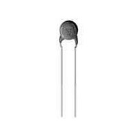
DEBF33A103ZA2B Murata, DEBF33A103ZA2B Datasheet - Page 18

DEBF33A103ZA2B
Manufacturer Part Number
DEBF33A103ZA2B
Description
Ceramic Disc Capacitors 0.01uF 1000volts F +80-20%
Manufacturer
Murata
Series
DEBr
Type
Ceramic Discr
Datasheet
1.DEBF33A103ZA2B.pdf
(72 pages)
Specifications of DEBF33A103ZA2B
Voltage Rating
1 KVolts
Operating Temperature Range
- 25 C to + 85 C
Termination Style
Radial
Product
High Voltage Ceramic Disc Capacitors
Dimensions
10 mm Dia.
Capacitance
0.01 uF
Tolerance
20 %
Temperature Coefficient
F
Lead Spacing
5 mm
Capacitance Tolerance
+80, -20%
Capacitor Case Style
Radial Leaded
No. Of Pins
2
Capacitor Mounting
Through Hole
Rohs Compliant
Yes
Tolerance (+ Or -)
-20% to 80%
Voltage
1000VDC
Temp Coeff (dielectric)
F
Operating Temp Range
-25C to 85C
Mounting Style
Through Hole
Package / Case
Not Required
Construction
Radial
Lead Spacing (nom)
5mm
Product Length (mm)
Not Requiredmm
Product Depth (mm)
4mm
Product Height (mm)
Not Requiredmm
Product Diameter (mm)
10mm
Lead Diameter (nom)
0.6mm
Seated Plane Height
13mm
Lead Free Status / RoHS Status
Lead free / RoHS Compliant
Available stocks
Company
Part Number
Manufacturer
Quantity
Price
Company:
Part Number:
DEBF33A103ZA2B
Manufacturer:
MURATA
Quantity:
37 584
5
!Note
• This PDF catalog is downloaded from the website of Murata Manufacturing co., ltd. Therefore, it’s specifications are subject to change or our products in it may be discontinued without advance notice. Please check with our
• This PDF catalog has only typical specifications because there is no space for detailed specifications. Therefore, please approve our product specifications or transact the approval sheet for product specifications before ordering.
sales representatives or product engineers before ordering.
!Note
1. Coated with flame-retardant epoxy resin (conforming
2. Cost-saving automatic insertion available.
3. This type is based on the electrical appliance and
Ideal for use on AC line filter and primary-secondary
coupling for switching power supplies and AC adapters.
16
Manufactured Date Code
DEJE3E2102Zppp
DEJE3E2222Zppp
DEJE3E2332Zppp
DEJE3E2472Zppp
DEJF3E2472Zppp
DEJF3E2103Zppp
Three blank columns are filled with the lead and packaging codes. Please refer to the 3 columns on the right for the appropriate code.
Taping (1): Lead spacing F=5.0mm, Taping (2): Lead spacing F=7.5mm.
Safety Recognized/High Voltage Ceramic Capacitors
DEJ Series -Based on the Electrical Appliance and Material Safety Law of Japan-
Capacitance Tolerance
Features
to UL94V-0 standard).
material safety law of Japan (separated table 4).
Applications
Marking
Nominal Capacitance
Part Number
• Please read rating and !CAUTION (for storage, operating, rating, soldering, mounting and handling) in this catalog to prevent smoking and/or burning, etc.
• This catalog has only typical specifications because there is no space for detailed specifications. Therefore, please approve our product specifications or transact the approval sheet for product specifications before ordering.
Manufacturer's
Identification
Rated Voltage
ø9-11mm
ø7-8mm
Temp. Char.
AC Rated
Voltage
(Vac)
250
250
250
250
250
250
Marked with
(omitted for nominal body diameter ø8mm and under)
Temp.
Char.
Marked with 3 figures
E
E
E
E
F
F
Marked with code
Marked with code
Abbreviation
10000 +80/-20% 11 max.
1000 +80/-20%
2200 +80/-20%
3300 +80/-20%
4700 +80/-20% 11 max.
4700 +80/-20%
102Z
250~
332Z
250~
Capacitance
E, F
65
65
(pF)
7 max.
8 max.
9 max.
8 max.
Dia. D
Body
(mm)
Spacing F
Lead
(mm)
7.5
7.5
7.5
7.5
7.5
7.5
Vertical Crimp Short (B3)
Vertical Crimp Long (A3)
Straight Short (D3)
Straight Long (C3)
Thickness T
4.0 max.
4.0 max.
4.0 max.
4.0 max.
4.0 max.
4.0 max.
Body
(mm)
[Bulk]
[Bulk]
Long Bulk
Package
Lead
C3B
A3B
A3B
A3B
A3B
A3B
Lead Code Coating Extension e
Lead Code Coating Extension e
e
A3
C3
B3
D3
F 1.0
Short Bulk
D max.
e
F 0.8
Package
Lead
D3B
B3B
B3B
B3B
B3B
B3B
Up to the end of crimp
Up to the end of crimp
D max.
ø d
3.0 max.
3.0 max.
ø d
Taping (1)
Package
<Fig. 1>
T max.
Lead
N2A
N2A
N2A
N2A
N2A
N2A
<Fig. 1>
T max.
0.6 0.05
0.6 0.05
0.6 0.05
0.6 0.05
ø d
ø d
Taping (2)
Package
<Fig. 2>
Lead
T max.
P3A
N3A
N3A
N3A
N3A
N3A
<Fig. 2>
(in mm)
(in mm)
T max.
Fig. 1
Fig. 2
Fig. 1
Fig. 2
Style
Style
C85E.pdf
08.10.29


