VJ0603A2R7BXACW1BC Vishay, VJ0603A2R7BXACW1BC Datasheet
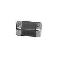
Multilayer Ceramic Capacitors (MLCC) - SMD/SMT 0603 2.7pF 50volts C0G +/-0.1pF

VJ0603A2R7BXACW1BC

Manufacturer Part Number
VJ0603A2R7BXACW1BC
Description
Multilayer Ceramic Capacitors (MLCC) - SMD/SMT 0603 2.7pF 50volts C0G +/-0.1pF
Manufacturer
Vishay
Series
VJ0603r
Datasheet

Specifications of VJ0603A2R7BXACW1BC

Voltage Rating
50 Volts
Operating Temperature Range
- 55 C to + 125 C
Temperature Coefficient / Code
C0G (NP0)
Product
General Type MLCCs
Dimensions
0.8 mm W x 1.6 mm L x 0.87 mm H
Termination Style
SMD/SMT
Capacitance
2.7 pF
Tolerance
0.1 pF
Package / Case
0603 (1608 metric)
Lead Free Status / RoHS Status
Lead free / RoHS Compliant
ELECTRICAL SPECIFICATIONS
Note:
Electrical characteristics at + 25 °C unless otherwise specified
Operating Temperature: - 55 °C to + 125 °C
Capacitance Range: 0.5 pF to 0.039 µF
Voltage Range: 10 Vdc to 100 Vdc
Temperature Coefficient of Capacitance (TCC):
0 ± 30 ppm/°C from - 55 °C to + 125 °C
Dissipation Factor (DF):
Cap. < 30 pF: Q 400 + 20C
Cap. ≥ 30 pF: Q ≥ 1000
Test Conditions:
Cap. ≤ 1000 pF 1.0 ± 0.2 V
Cap. > 1000 pF 1.0 ± 0.2 V
Document Number: 28501
Revision: 30-Jul-09
ORDERING INFORMATION
VJ0402
CODE
SIZE
0402
0603
0805
1206
A = C0G (NP0)
DIELECTRIC
Surface Mount Multilayer Ceramic Chip Capacitors
A
rms
rms
Two significant digits
, 1 MHz ± 10 %
, 1 kHz ± 10 %
number of zeros:
103 = 10 000 pF
CAPACITANCE
followed by the
102 = 1000 pF
152 = 1500 pF
101 = 100 pF
101
for Commodity Applications
For technical questions, contact:
TOLERANCE TERMINATION
B = ± 0.10 pF
C = ± 0.25 pF
D = ± 0.50 pF
Cap. < 10 pF
Cap. ≥ 10 pF
K = ± 10 %
G = ± 2 %
F = ± 1 %
J = ± 5 %
J
X = Ni Barrier
VJ....W1BC C0G (NP0) Dielectric
FEATURES
• Ultra stable class 1 dielectric
• Four standard sizes
• High capacitance per unit volume
• Supplied in tape on reel
• For high frequency applications
• Ni-barrier with 100 % tin terminations
• Dry sheet manufacturing technology
• Halogen-free according to IEC 61249-2-21 definition
• Compliant to RoHS directive 2002/95/EC
APPLICATIONS
• Consumer electronics
• Telecommunications
• Data processing
Aging Rate: 0 % maximum per decade
Insulation Resistance (IR): after 120 s at U
10 GΩ or 500 ΩF whichever is less
Dielectric Strength Test:
This is the maximum voltage the capacitors are tested
1 s to 5 s period and the charge/discharge current does not
exceed 50 mA
≤ 100 Vdc: 250 % of rated voltage
X
mlcc@vishay.com
VOLTAGE
B = 100 V
Q = 10 V
X = 25 V
A = 50 V
J = 16 V
Q
PACKAGING
P = 13" reel/
R = 13" reel/
C = 7" reel/
plastic tape
plastic tape
T = 7" reel/
paper tape
paper tape
C
PROCESS CODE
COMMODITY
FOR BASIC
R
www.vishay.com
(DC):
W1BC
Vishay
1

Related parts for VJ0603A2R7BXACW1BC

VJ0603A2R7BXACW1BC Summary of contents

Page 1

... C = ± 0. ± 0.50 pF Cap. ≥ ± ± ± ± For technical questions, contact: mlcc@vishay.com Vishay (DC W1BC VOLTAGE PACKAGING PROCESS CODE FOR BASIC COMMODITY 7" reel paper tape 13" reel paper tape B = 100 7" reel/ plastic tape R = 13" reel/ plastic tape www.vishay.com 1 ...

Page 2

... Note • Letters indicate product thickness, see Packaging Quantities www.vishay.com 2 for Commodity Applications NP0 0603 For technical questions, contact: mlcc@vishay.com 0805 1206 ...

Page 3

... PLASTIC TAPE 13" reel (P) 7" reel (T) 13" reel (R) 50K 15K 15K 15K 15K 3K 15K www.vishay.com Vishay MB 10K 10K 10K 10K 8K 3 ...

Page 4

... REEL DIMENSIONS AND TAPE WIDTH in millimeters For technical questions, contact: mlcc@vishay.com PRODUCT SIZE CODE 0402 0603 0805 0.62 ± 0.05 1.02 ± 0.05 1.50 ± 0.10 1.12 ± 0.05 1.82 ± 0.05 2.30 ± 0.10 8.00 ± 0.10 8.00 ± 0.10 8.00 ± ...

Page 5

... Vishay disclaims any and all liability arising out of the use or application of any product described herein or of any information provided herein to the maximum extent permitted by law. The product specifications do not expand or otherwise modify Vishay’ ...

Related keywords