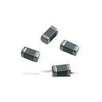
BLM21BD272SH1L Murata, BLM21BD272SH1L Datasheet - Page 64

BLM21BD272SH1L
Manufacturer Part Number
BLM21BD272SH1L
Description
EMI/RFI Suppressors & Ferrites 0805 2.7Kohms HiSpd Signal Line Tape
Manufacturer
Murata
Series
BLM Br
Datasheet
1.BLM18AG471SH1D.pdf
(93 pages)
Specifications of BLM21BD272SH1L
Shielding
Unshielded
Test Frequency
100 MHz
Product
Chip Ferrite Beads
Impedance
2.7 KOhms
Tolerance
25 %
Maximum Dc Current
200 mAmps
Maximum Dc Resistance
0.8 Ohms
Operating Temperature Range
- 55 C to + 125 C
Package / Case
0805 (2012 metric)
Termination Style
SMD/SMT
Dc Resistance Max
0.8ohm
Dc Current Rating
200mA
Ferrite Mounting
SMD
Ferrite Case Style
0805 / 2012
Operating Temperature Max
+125°C
Operating Temperature Min
-55°C
Rohs Compliant
Yes
Lead Free Status / RoHS Status
Lead free / RoHS Compliant
Available stocks
Company
Part Number
Manufacturer
Quantity
Price
Company:
Part Number:
BLM21BD272SH1L
Manufacturer:
MURATA
Quantity:
240 000
4
!Note
• This PDF catalog is downloaded from the website of Murata Manufacturing co., ltd. Therefore, it’s specifications are subject to change or our products in it may be discontinued without advance notice. Please check with our
• This PDF catalog has only typical specifications because there is no space for detailed specifications. Therefore, please approve our product specifications or transact the approval sheet for product specifications before ordering.
sales representatives or product engineers before ordering.
!Note
c
<Unless otherwise specified>
c
1. Electrical Performance
62
No.
BNX012H series Specifications and Test Methods
1
2
3
4
5
Temperature: Ordinary Temp. 15 to 35 C
Humidity: Ordinary Humidity 25 to 85% (RH)
Test and Measurement Conditions
Specifications
• Please read rating and !CAUTION (for storage, operating, rating, soldering, mounting and handling) in this catalog to prevent smoking and/or burning, etc.
• This catalog has only typical specifications because there is no space for detailed specifications. Therefore, please approve our product specifications or transact the approval sheet for product specifications before ordering.
Insulation Resistance
Dielectric Strength
Capacitance
Insertion Loss
Voltage Drop
Item
500M min.
Filter should not fail.
1.0 F 15%
40dB min. (1MHz to 1GHz)
35mV max.
Specifications
<In case of doubt>
Temperature: 20 C 2 C
Humidity: 60 to 70% (RH)
Atmospheric pressure: 86 to 106kPa
Specifications and Test Methods
Measured at DC rated voltage between terminal (1)(2) and
(3)(4).
Voltage: 50Vdc
Charging time: 2 minutes
Suitable resistor: 1M
Test voltage should be applied between terminal (1)(2) and
(3)(4).
Test Voltage: 125Vdc
Testing Time: 1 to 5s
Charge/Discharge Current: 50mA max.
Measured at the following conditions between terminal (1)(2)
and (3)(4).
Frequency: 1.0 0.1kHz
Voltage: 1Vrms max.
Measured by the following circuit.
Measuring Equipment: R3767 C (manufactured by
ADVANTEST) or the equivalent.
Sample: build product into Balun.
Rated Current: 15 A
Substrate: 100x100x1.6mm (paper-phenol)
Soldering: Insert the terminals into the holes on P.C. board
Voltage Drop Value: V1+V2
Probe of each voltmeter should contact the center of soldering
parts as shown in the following figure.
(*): It uses the Balun or 1 to 1 transformer.
NETWORK ANALYZER
Port 1 (50 )
Copper foil pattern
Paper-phenol
Substrate
(3)
completely.
(1)
A
Balun (*) Product
Solder
Test Methods
1
3 4
2
(4)
(2)
Continued on the following page.
(2)
V1
V2
(3)
(1)
Port 2 (50 )
(3)
Product
Product’s Terminal
Substrate
(1) to (4): Terminal
Probe
C50E.pdf
1
08.8.28


