B66319GX187 EPCOS Inc, B66319GX187 Datasheet - Page 5

B66319GX187
Manufacturer Part Number
B66319GX187
Description
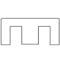
EMI/RFI Suppressors & Ferrites E30/15/7 N87OL
Manufacturer
EPCOS Inc
Series
B66319r
Specifications of B66319GX187
Shielding
Unshielded
Product
Solid Core Ferrite Suppressors
Tolerance
- 20 % to + 30 %
Ferrite Grade
N87
Core Size
E30
Al Tolerance Value +
30%
Al Tolerance Value -
20%
External Depth
7.3mm
External Length / Height
15.2mm
External Width
30mm
Inductance Factor Al
1900nH
Rohs Compliant
Yes
Svhc
No SVHC (20-Jun-2011)
Lead Free Status / RoHS Status
Lead free / RoHS Compliant
Other names
B66319G0000X187
Mechanical stress and mounting
Ferrite cores have to meet mechanical requirements during assembling and for a growing number
of applications. Since ferrites are ceramic materials one has to be aware of their special behavior
under mechanical load.
Just like any ceramic material, ferrite cores are brittle and sensitive to any shock, fast changing or
tensile load. Especially fast cooling rates under ultrasonic cleaning, high static and cyclic loads can
cause cracks or failure of the ferrite cores.
For detailed information see Data Book 2007, chapter "General - Definitions, 8.1".
Effects of core combination on A
Stresses in the core affect not only the mechanical but also the magnetic properties. It is apparent
that the initial permeability is dependent on the stress state of the core. The higher the stresses are
in the core, the lower the value for the initial permeability. Thus, the embedding medium should offer
the greatest possible elasticity.
For detailed information see Data Book 2007, chapter "General - Definitions, 8.2".
Heating up
Ferrites can run hot during operation at higher flux densities and higher frequencies.
NiZn-materials
The magnetic properties of NiZn-materials can change irreversibly when exposed to strong
magnetic fields.
Processing notes
– The start of the winding process should be soft. Otherwise, the flanges may be destroyed.
– Excessive winding forces may damage the flanges or squeeze the tube so that the cores can no
– Excessive soldering time at high temperature (>300 °C) may affect coplanarity or pin
– Not following the processing notes for soldering of the J-leg terminals may cause solderability
– The dimensions of the pin hole arrangement are fixed and should be understood as an ideal
Ferrites and accessories
Cautions and warnings
longer be mounted.
arrangement.
problems at the transformer because of contamination with tin oxide (SnO) from the tin bath or
burned insulation from the wire. For detailed information see Data Book 2007, chapter
"Processing notes, 2.2".
recommendation for drilling the printed circuit board. In order to avoid problems when mounting
the transformer, customers should make allowances for manufacturing tolerances in the drilling
and pick-and-place processes by increasing the diameter of the pin holes.
L
value
5
01/10


