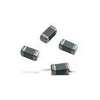
BLM21PG221SN1D Murata, BLM21PG221SN1D Datasheet - Page 143

BLM21PG221SN1D
Manufacturer Part Number
BLM21PG221SN1D
Description
EMI/RFI Suppressors & Ferrites 0805 220 OHM
Manufacturer
Murata
Type
Chip Beadr
Specifications of BLM21PG221SN1D
Shielding
Unshielded
Test Frequency
100 MHz
Product
Chip Ferrite Beads
Impedance
220 Ohms
Tolerance
25 %
Maximum Dc Current
2000 mAmps
Maximum Dc Resistance
0.05 Ohms
Operating Temperature Range
- 55 C to + 125 C
Package / Case
0805 (2012 metric)
Termination Style
SMD/SMT
Inductance
Not RequireduH
Core Material
Ferrite
Tolerance (+ Or -)
25%
Dc Resistance
50mOhm
Case Size (inches)
0805in
Operating Temp Range
-55C to 125C
Dc Current
2A
Product Diameter (mm)
Not Requiredmm
Product Height (mm)
1.05mm
Product Depth (mm)
1.25mm
Product Length (mm)
2.2mm
Military Standard
Not Required
Failure Rate
Not Required
Dc Resistance Max
0.05ohm
Dc Current Rating
2A
No. Of Pins
2
Operating Temperature Min
-55°C
Resistance
0.05ohm
Operating Temperature Max
+125°C
Rohs Compliant
Yes
Ferrite Mounting
SMD
Ferrite Case Style
0805 / 2012
Lead Free Status / RoHS Status
Lead free / RoHS Compliant
Available stocks
Company
Part Number
Manufacturer
Quantity
Price
Company:
Part Number:
BLM21PG221SN1D
Manufacturer:
MURATA
Quantity:
600 000
Company:
Part Number:
BLM21PG221SN1D
Manufacturer:
Murata Electronics North Ameri
Quantity:
518 573
Part Number:
BLM21PG221SN1D
Manufacturer:
MURATA/村田
Quantity:
20 000
NFp Chip EMIFILr
!Note
2. Solder Paste Printing and Adhesive Application
NFM
NFR
NFL
When reflow soldering the chip EMI suppression filter, the
printing must be conducted in accordance with the
following cream solder printing conditions.
If too much solder is applied, the chip will be prone to
damage by mechanical and thermal stress from the PCB
and may crack.
Standard land dimensions should be used for resist and
copper foil patterns.
• Please read rating and !CAUTION (for storage, operating, rating, soldering, mounting and handling) in this catalog to prevent smoking and/or burning, etc.
• This catalog has only typical specifications because there is no space for detailed specifications. Therefore, please review our product specifications or consult the approval sheet for product specifications before ordering.
Series
NFM18C/18PC
NFL18ST
NFM3DC/3DP
NFM41C/41P
NFM18PS
oGuideline of solder paste thickness:
0.05
Soldering and Mounting
100-150 m: NFM18/21/3D/31P, NFR, NFL
150-200 m: NFM55P
100-200 m: NFM41
1.0
2.2
0.4
1.0
2.5
3.9
1.5
3.5
5.5
0.8
1.2
2.0
Solder Paste Printing
NFL18SP
NFM21C/21PC
NFR21G/NFL21S
NFM31P
NFM55P
1.0
2.0
1.5
4.7
6.7
0.4
1.4
0.6
2.6
4.4
1.0
2.5
When flow soldering the EMI suppression filter, apply the
adhesive in accordance with the following conditions.
If too much adhesive is applied, then it may overflow into
the land or termination areas and yield poor solderability.
In contrast, if insufficient adhesive is applied, or if the
adhesive is not sufficiently hardened, then the chip may
become detached during flow soldering process.
NFM3D/31P/41 Series
Apply 0.1mg for NFM41C/41 and 0.06mg for
NFM3D/NFM31P of bonding agent at each chip.
Do not cover electrodes.
Bonding agent
Adhesive Application
Continued on the following page.
Coating position of
bonding agent
(in mm)
141
Mar.28,2011
C31E.pdf


