CSC10A035K60GPA Vishay, CSC10A035K60GPA Datasheet
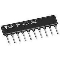
Resistor Networks & Arrays 10pin 5.6Kohms 2% Isolated

CSC10A035K60GPA

Manufacturer Part Number
CSC10A035K60GPA
Description
Resistor Networks & Arrays 10pin 5.6Kohms 2% Isolated
Manufacturer
Vishay
Series
CSCr
Datasheet

Specifications of CSC10A035K60GPA

Product Type
Networks
Circuit Type
Isolated
Number Of Resistors
5
Resistance
5.6 KOhms
Tolerance
2 %
Power Rating
0.3 Watt
Temperature Coefficient
+/- 250 PPM / C
Number Of Pins
10
Operating Temperature Range
- 55 C to + 125 C
Dimensions
0.195 mm Dia. x 7.5 mm W x 25.15 mm L x 2.49 mm H
Lead Spacing
2.54 mm
Termination Style
SIP
Resistor Values
5.6 KOhms
Lead Free Status / RoHS Status
Lead free / RoHS Compliant
www.vishay.com
1
CSC
Vishay Dale
Notes
• See derating curves for package power rating
(1)
(2)
(3)
GLOBAL
GLOBAL
MODEL
MODEL
STANDARD ELECTRICAL SPECIFICATIONS
GLOBAL
MODEL/
SCHEMATIC
CSCxxx01
CSCxxx03
CSCxxx05
GLOBAL PART NUMBER INFORMATION
New Global Part Numbering: CSC08A03100RGEK (preferred part number format)
Historical Part Number example: CSC08A03101GEK (will continue to be accepted)
New Global Part Numbering: CSC08A05131AGEK (preferred part number format)
Historical Part Number example: CSC08A05131AGEK (will continue to be accepted)
HISTORICAL
For resistor power ratings at + 25 °C see derating curves
± 2 % standard, ± 1 % and ± 5 % available
Continuous working voltage shall be
CSC
CSC
HISTORICAL
MODEL
C
C
MODEL
CSC
CSC
PIN COUNT
PIN COUNT
04 to 12 pin
04 to 12 pin
12 = 12 pin
12 = 12 pin
S
S
04 = 4 pin
08 = 8 pin
04 = 4 pin
08 = 8 pin
available
available
PACKAGE
HEIGHT
PIN COUNT
C
C
A
B
A
B
A
B
Thick Film Resistor Networks, Single-In-Line,
PIN COUNT
08
A = “A” profile
B = “B” profile
A = “A” profile
B = “B” profile
0
0
08
PACKAGE
PACKAGE
POWER RATING
HEIGHT
HEIGHT
ELEMENT
P
8
8
70 °C
0.20
0.25
0.30
0.40
0.20
0.25
PACKAGE
HEIGHT
P x R
W
For technical questions, contact:
A
A
A
(1)
SCHEMATIC
03 = Isolated
SCHEMATIC
01 = Bussed
00 = Special
PACKAGE
HEIGHT
terminator
05 = Dual
Conformal Coated SIP
or maximum working voltage, whichever is less
A
RESISTANCE
50.1 to 2.2M
50.1 to 2.2M
50.1 to 2.2M
0
0
RANGE
10 to 50
10 to 50
10 to 50
SCHEMATIC
Ω
3
5
3 digit impedance
code, followed by
05
1M00 = 1.0 MΩ
680K = 680 kΩ
(see impedance
RESISTANCE
RESISTANCE
alpha modifier
10R0 = 10 Ω
codes table)
SCHEMATIC
M = MΩ
VALUE
K = kΩ
VALUE
R = Ω
TEMP. COEFFICIENT
1
1
(- 55 °C to + 125 °C)
03
RESISTANCE
± ppm/°C
0
3
ff2aresistors@vishay.com
FEATURES
• Isolated, bussed and dual terminator schematics
• Body height: “A” profile = 0.195" (4.95 mm) and
• “A” profile standard in 4 thru 12 pins
• Thick film resistive elements
• Reduces total assembly costs
• Resistor elements protected by tough epoxy
• Wide resistance range (10 Ω to 2.2 MΩ)
• Available in bulk pack as standard; optional tube pack is
• Meets EIA/ECA-CB23 rev. G whisker test requirements for
• Compliant to RoHS directive 2002/95/EC
VALUE 1
250
100
250
100
250
100
available
“B” profile = 0.295" (7.50 mm) standard; custom
“C” profile = 0.350" (8.89 mm) also available
conformal coating
also available
Class 1A products
221
TOLERANCE
TOLERANCE
S = Special
G = ± 2 %
G = ± 2 %
F = ± 1 %
F = ± 1 %
J = ± 5 %
J = ± 5 %
0
1
CODE
CODE
RESISTANCE
VALUE
R
A
101
RESISTANCE
TOL.
1, 2, 5
1, 2, 5
1, 2, 5
± %
VALUE 2
EK = Lead (Pb)-free, bulk
331
G
G
(2)
PA = Tin/lead, bulk
PA = Tin/lead, bulk
(- 55 °C to + 125 °C)
TCR TRACKING
PACKAGING
PACKAGING
E
E
TOLERANCE
± ppm/°C
CODE
TOLERANCE
150
50
50
G
K
K
CODE
G
Document Number: 31509
(1)
Revision: 07-Jun-10
MAX. WORKING
Blank = Standard
Blank = Standard
(Dash Number)
(Dash Number)
(Up to 3 digits)
(Up to 3 digits)
From 1 to 999
PACKAGING
From 1 to 999
VOLTAGE
as applicable
as applicable
PACKAGING
SPECIAL
SPECIAL
EK
V
100
100
100
EK
DC
(3)

Related parts for CSC10A035K60GPA

CSC10A035K60GPA Summary of contents

Page 1

... CSC Vishay Dale Thick Film Resistor Networks, Single-In-Line, STANDARD ELECTRICAL SPECIFICATIONS GLOBAL POWER RATING PACKAGE MODEL/ ELEMENT HEIGHT P SCHEMATIC 70 °C A 0.20 CSCxxx01 B 0.25 A 0.30 CSCxxx03 B 0.40 A 0.20 CSCxxx05 B 0.25 Notes • See derating curves for package power rating (1) For resistor power ratings °C see derating curves (2) ± ...

Page 2

... CSC09 14 0.890 (22.61) n CSC10 16 0.990 (25.15) CSC11 18 CSC12 20 For technical questions, contact: ff2aresistors@vishay.com Vishay Dale CSC SERIES < 50 ppm typical 200 > 100M - 125 0.098 (2.49) Max. 0.045 (1.14) 0.012 ± 0.003 (0.305 ± 0.076) (Leads are along centerline of body (Maximum) 0 ...

Page 3

... CSC Thick Film Resistor Networks, Single-In-Line, Vishay Dale MECHANICAL SPECIFICATIONS Marking Resistance Permanency testing per to Solvents MIL-STD-202, method 215 Per MIL-STD-202, method 208E, Solderability Body High alumina, epoxy coated Terminals Solder plated leads IMPEDANCE CODES CODE R (Ω) 1 500B 82 750B 120 800C ...

Page 4

... Derated according to the curve. 4.5 pound pull for 000 MΩ (minimum) No evidence of arcing or damage (200 V For technical questions, contact: ff2aresistors@vishay.com Vishay Dale Bussed • Open Collector Pull-up • TTL Input Pull-down • TTL Unused Gate Pull-up Isolated • Long-Line Impedance Balancing • ...

Page 5

... Vishay product could result in personal injury or death. Customers using or selling Vishay products not expressly indicated for use in such applications their own risk and agree to fully indemnify and hold Vishay and its distributors harmless from and against any and all claims, liabilities, expenses and damages arising or resulting in connection with such use or sale, including attorneys fees, even if such claim alleges that Vishay or its distributor was negligent regarding the design or manufacture of the part ...

Related keywords