PV36W203C01B00 Murata, PV36W203C01B00 Datasheet - Page 8
PV36W203C01B00
Manufacturer Part Number
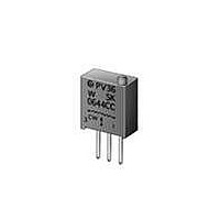
PV36W203C01B00
Description
Trimmer Resistors - Multi Turn 20Kohms 10mm Square 25turn
Manufacturer
Murata
Datasheets
1.PV36W102C01B00.pdf
(14 pages)
2.PV36W103C01B00.pdf
(22 pages)
3.PVG5A201C01R00.pdf
(90 pages)
Specifications of PV36W203C01B00
Resistance
20 KOhms
Power Rating
0.5 Watt (1/2 Watt)
Operating Temperature Range
- 55 C to + 125 C
Element Type
Cermet
Product
Multi-Turn Trimmer Potentiometers
Tolerance
10 %
Number Of Turns
25
Taper
Linear
Lead Free Status / RoHS Status
Lead free / RoHS Compliant
Available stocks
Company
Part Number
Manufacturer
Quantity
Price
Company:

Part Number:
PV36W203C01B00
Manufacturer:
MURATA
Quantity:
240 000


!Note
!Note
1. Store in temperatures of -10 to +40 deg. C and
2. Do not store in or near corrosive gases.
3. Use within six months after delivery.
4. Open the package just before using.
5. Do not store under direct sunlight.
6. If you use the trimmer potentiometer in an
1. When using with partial load (rheostat), minimize
2. The maximum input voltage to a trimmer
3. The maximum input current to a trimmer
4. If the trimmer potentiometer is used in DC and high
1. Soldering
(1) Reflow soldering and Soldering Iron are
(2) Use our standard land dimension. Excessive land
(3) Standard soldering condition
(4) Apply the appropriate amount of solder paste.
the power depending on the resistance value.
potentiometer should not exceed (P.R)^1/2 or the
maximum operating voltage, whichever is smaller.
potentiometer should not exceed (P/R)^1/2 or the
allowable wiper current, whichever is smaller.
humidity conditions, please connect wiper (#2) for
plus and resistive element (#1 or #3) for minus.
Notice (Operating and Storage Conditions)
relative humidity of 30-85%RH.
environment other than listed below, please
consult with a Murata factory representative prior
to using.
The trimmer potentiometer should not be used under
Notice (Rating)
Notice (Soldering and Mounting)
(a) Reflow soldering :
(b) Soldering iron:
available. Cannot be soldered using the flow
soldering method. If you use the flow soldering
method, the trimmer potentiometer may not
function.
area causes displacement due to the effect of the
surface tension of the solder. Insufficient
land area leads to insufficient soldering
strength of the chip.
Before using other soldering conditions than
those listed above, please consult with Murata
factory representative prior to using. If the
soldering conditions are not suitable, e.g.,
excessive time and/or excessive temperature, the
trimmer potentiometer may deviate from the
specified characteristics.
• Please read rating and !CAUTION (for storage, operating, rating, soldering, mounting and handling) in this catalog to prevent smoking and/or burning, etc.
• This catalog has only typical specifications because there is no space for detailed specifications. Therefore, please approve our product specifications or transact the approval sheet for product specifications before ordering.
Please read rating and !CAUTION (for storage, operating, rating, soldering, mounting and handling) in this PDF catalog to prevent smoking and/or burning, etc.
This catalog has only typical specifications. Therefore, you are requested to approve our product specifications or to transact the approval sheet for product specifications before ordering.
>Temperature of tip 360 deg. C max.
>Soldering time
>Diameter
>Wattage of iron
Refer to the standard temperature profile.
30W max.
1mm max.
3 sec. max.
2. Mounting
3. Cleaning
(1) Corrosive gaseous atmosphere
(2) In liquid
(3) Dusty / dirty atmosphere
(4) Direct sunlight
(5) Static voltage nor electric/magnetic fields
(6) Direct sea breeze
(7) Other variations of the above
(5) The soldering iron should not come in contact
(1) Do not apply excessive force (preferably 4.9N
(2) Do not warp and/or bend PC board to prevent
(3) In chip placers, the recommended size of the
(1) In case there is flux on the resistive element,
(2) Isopropyl-alcohol and Ethyl-alcohol are
the following environmental conditions:
(Ex. Chlorine gas, Hydrogen sulfide gas, Ammonia
gas, Sulfuric acid gas, Nitric oxide gas, etc.)
(Ex. Oil, Medical liquid, Organic solvent, etc.)
The thickness of solder paste should be printed
from 100 micro m to 150 micro m and the
dimension of land pattern used should be Murata's
standard land pattern at reflow soldering.
Insufficient amounts of solder can lead to
insufficient soldering strength on PCB.
Excessive amounts of solder may cause bridging
between the terminals.
with the case of the trimmer potentiometer. If
such contact does occur, the trimmer
potentiometer may be damaged.
(Ref.; 500gf) max.), when the trimmer
potentiometer is mounted to the PCB.
trimmer potentiometer from breakage.
cylindrical pick-up nozzle should be outer
dimension 1.5-1.8mm dia. and inner dimension
1.3mm dia.
clean sufficiently with cleaning solvents and
completely remove all residual flux.
PVZ2 Series Notice
Continued on the following page.
R50E13.pdf 04.6.11
7
1
Related parts for PV36W203C01B00
Image
Part Number
Description
Manufacturer
Datasheet
Request
R

Part Number:
Description:
Murata Microblower 20x20 DCDC Driver Board - Samples Only
Manufacturer:
Murata
Part Number:
Description:
357-036-542-201 CARDEDGE 36POS DL .156 BLK LOPRO
Manufacturer:
Murata
Datasheet:
Part Number:
Description:
Manufacturer:
Murata
Datasheet:
Part Number:
Description:
Manufacturer:
Murata
Datasheet:
Part Number:
Description:
Manufacturer:
Murata
Datasheet:
Part Number:
Description:
Manufacturer:
Murata
Datasheet:
Part Number:
Description:
Manufacturer:
Murata
Datasheet:
Part Number:
Description:
Manufacturer:
Murata
Datasheet:
Part Number:
Description:
Manufacturer:
Murata
Datasheet:
Part Number:
Description:
BLM21BD751SN1On-Board Type (DC) EMI Suppression Filters
Manufacturer:
Murata
Datasheet:
Part Number:
Description:
BLM15AG100SN1On-Board Type (DC) EMI Suppression Filters
Manufacturer:
Murata
Datasheet:
Part Number:
Description:
NFE31PT222Z1E9On-Board Type (DC) EMI Suppression Filters
Manufacturer:
Murata
Datasheet:
Part Number:
Description:
Chip Coil
Manufacturer:
Murata
Datasheet:
Part Number:
Description:
Chip Coil
Manufacturer:
Murata
Datasheet: