FMS.0M.305.XLMT LEMO, FMS.0M.305.XLMT Datasheet - Page 8
FMS.0M.305.XLMT
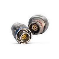
Manufacturer Part Number
FMS.0M.305.XLMT
Description
Circular Metric Connectors 5P STRT PLUG FEMALE CRIMP KNURLED GRIP
Manufacturer
LEMO
Series
M Seriesr
Datasheet
1.PEN.0M.305.XLMT.pdf
(8 pages)
Specifications of FMS.0M.305.XLMT
Product Type
Connectors
Contact Style
Socket (Female)
Shell Style
Plug
Number Of Contacts
5
Mounting Style
Cable
Termination Style
Crimp
Contact Plating
Nickel / Gold
Current Rating
6.5 A
Voltage Rating
1.25 kV
Mating Style
Ratchet
Ingress Protection
IP68
Lead Free Status / RoHS Status
Lead free / RoHS Compliant


Assembly instructions for plugs and sockets (with optional mold stop)
© CAT.MM.LEN.P0509
LEMO
SWITZERLAND
LEMO SA
Chemin des Champs-Courbes 28 - P.O. Box 194 - CH-1024 Ecublens
Tel. (+41 21) 695 16 00 - Fax (+41 21) 695 16 02 - e-mail: info@lemo.com
www.lemo.com
HEADQUARTERS
1
1
CHF 1.50 / EURO 1 / USD 1.1 / RMB 10
L
S
T
± 0.5
± 0.5
± 0.2
Crimp
Crimp
Steel tie-wrap band (~3 mm wide)
Steel tie-wrap band (~3 mm wide)
Overmolding
Overmolding
FG
PH
PB
●
●
●
1.
2.
2.1 With shielded cables, widen and pull the shield all the way
2.2 Arrange the conductor-contact assemblies according to
2.3 Bring the shield around the rear of connector until the mold
2.4 Custom overmold cable assembly.
Cable preparation
Strip the cable accor ding to
dimensions of the table,
then widen the shield.
Cable termination
to the back.
Fix the appropriate positioner onto the crimping tool and set
the selector to the number corresponding to the AWG of
the conductor used as indicated on the positioner label. Fit
the conductor into the contact
through the contact’s inspection hole.
Slide the conductor-contact assembly into the open
crimping tool; make sure that the contact is pushed fully
into the positioner. Close the tool.
Remove from crimping tool and check that conductor is
secure in contact and shows in inspection hole.
the markings, into the rear cable seal. Push them deeply
into the insulator, using tweezers if necessary; check that
all the contacts are correctly located in the insulator: 1) by
verifying the alignment of the contacts at the front of the
insulator and 2) by gently pulling on each conductor.
Verification should also be made using the appropriate
retention testing tool.
stop. Secure it with a band-it tie-wrap (not furnished) to fix
the shield in place.
Cut off the possible shield surplus.
1
1
Data subject to change, printed in Switzerland, May 2009
Note : dimensions are in mm.
➀
Series
0M
1M
2M
; make sure it is visible
Updated, February 2011
20
20
20
L
15
15
15
S
3.5
3.5
3.5
T
Related parts for FMS.0M.305.XLMT
Image
Part Number
Description
Manufacturer
Datasheet
Request
R

Part Number:
Description:
RF Connectors ADAPTOR SOCKET TO BNC PLUG
Manufacturer:
LEMO
Datasheet:

Part Number:
Description:
RF Connectors ADAPT-BNC(UG88U)COAX
Manufacturer:
LEMO
Datasheet:
Part Number:
Description:
RF Connectors BNC ADAPTER 50 OHM
Manufacturer:
LEMO
Datasheet:

Part Number:
Description:
LEMO, SPRING LOADED DUSTCAP
Manufacturer:
LEMO
Datasheet:

Part Number:
Description:
Circular Push Pull Connectors CONNECTOR WRENCH FOR LEMO
Manufacturer:
LEMO
Part Number:
Description:
THERMOELEMENT MIT MAGNETISCHEM STREIFEN
Manufacturer:
N/A
Part Number:
Description:
SIM Card Reader (Manual Insertion)
Manufacturer:
Yamaichi Electronics

Part Number:
Description:
Broadband Frequency Doubler/ 10 - 4800 MHz Output
Manufacturer:
Tyco Electronics
Datasheet:
Part Number:
Description:
Specifications: Connector Type: Plug, Male Pins ; Shell Size - Insert: 114 ; Mounting Type: Free Hanging (In-Line) ; Fastening Type: Threaded ; Features: Shielded ; Packaging: Bulk ; Number of Positions: 114 ; Termination: Crimp ; Shell Material, Fin
Manufacturer:
LEMO
Part Number:
Description:
Specifications: Connector Style: - ; Connector Type: Plug ; Simplex/Duplex: Duplex ; Mode: Singlemode ; Fiber Diameter: 125
Manufacturer:
LEMO