EGG.0B.304.CLL LEMO, EGG.0B.304.CLL Datasheet - Page 179
EGG.0B.304.CLL
Manufacturer Part Number
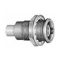
EGG.0B.304.CLL
Description
Circular Push Pull Connectors RECP SIZE 0 4-pin FEMALE SLDR
Manufacturer
LEMO
Series
B Seriesr
Datasheet
1.GMA.0B.030.DR.pdf
(186 pages)
Specifications of EGG.0B.304.CLL
Product Type
Connectors
Contact Style
Socket (Female)
Shell Style
Receptacle
Number Of Contacts
4
Termination Style
Solder
Shell Plating
Chrome Plated
Current Rating
7 A
Lead Free Status / RoHS Status
Lead free / RoHS Compliant


Contact resistance with relation to the number
of mating cyles
(measured according to IEC 60512-2 test 2a)
Average values measured after the mating cycles and the
salt spray test according to IEC 60512-6 test 11f.
Solder contacts
The conductor bucket of these contacts is machined at an
angle to form a cup into which the solder can flow.
See page 7 for the range of cable dimensions that can be
soldered.
Crimp contacts
The square form crimp method is used (MIL-C-22520F,
class I, type 2) photo 1 for unipole contacts.
For multipole contacts the standard four identer crimp
method is used, MIL-C-22520F, class I, type 1), photo 2.
The crimp method requires a controlled compression to
obtain a symmetrical deformation of the conductor strand and
of the contact material. The radial hole in the side of the con-
tact makes it possible to check whether the conductor is
correctly positioned within the contact. A good crimping is char-
acterized by only slightly reduced conductor section and
practically no gap.
For optimum crimping of bronze or brass contacts they are
annealed to relieve internal stress and reduce material
hardening during the crimping process.
Only the crimping zone is annealed with the help of an
induction heating machine designed by the LEMO Research
and Development Department (see photo 3).
Crimp contacts
The crimp contacts can be with two forms: a standard crimp
barrel for large conductors (see fig. 1) or with a reduced
crimp barrel for smaller conductors (see fig. 2).
www.lemo.com
(mm)
Fig. 1
A ø
0.5
0.7
0.9
1.3
1.6
2.0
cycles
1000
Contact resistance (mΩ)
7.5
5.6
4.1
2.8
2.6
2.9
cycles
3000
8.3
5.7
4.2
2.9
2.7
3.1
cycles
5000
8.7
6.1
4.8
3.6
3.5
3.3
(mm)
12.0
A ø
3.0
4.0
5.0
6.0
8.0
cycles
1000
Contact resistance (mΩ)
2.0
1.6
1.4
1.2
0.8
0.7
cycles
3000
2.2
2.0
–
–
–
–
cycles
5000
3.1
2.8
–
–
–
–
Insulation resistance between the contacts
and contact/shell
(measured according to IEC 60512-2 test 3a)
Note:
Advantages of crimping
– practical, quick contact fixing outside the insulator
– possible use at high temperature
– no risk of heating the insulator during the conductor-
– high tensile strength
Crimp contacts are available in standard version (form 1) for
mounting maximum size conductors.
For some dimensions, these crimp contacts can be pro-
duced with reduced crimp barrels (form 2) for mounting
reduced size conductors.
The range of cable dimensions that can be crimped into
our contacts are indicated on the table on page 7.
new
after humidity test
1
Fig. 2
contact fixing
Insulating material
1)
21 days at 95% RH according to IEC 60068-2-3.
1)
2
Multipole
> 10
> 10
PEEK
12
10
Ω
Ω
> 10
> 10
Unipole
PTFE
12
10
3
Ω
Ω
®
177
®
Related parts for EGG.0B.304.CLL
Image
Part Number
Description
Manufacturer
Datasheet
Request
R

Part Number:
Description:
RF Connectors ADAPTOR SOCKET TO BNC PLUG
Manufacturer:
LEMO
Datasheet:

Part Number:
Description:
RF Connectors ADAPT-BNC(UG88U)COAX
Manufacturer:
LEMO
Datasheet:
Part Number:
Description:
RF Connectors BNC ADAPTER 50 OHM
Manufacturer:
LEMO
Datasheet:

Part Number:
Description:
LEMO, SPRING LOADED DUSTCAP
Manufacturer:
LEMO
Datasheet:

Part Number:
Description:
Circular Push Pull Connectors CONNECTOR WRENCH FOR LEMO
Manufacturer:
LEMO
Part Number:
Description:
Specifications: Connector Type: Plug, Male Pins ; Shell Size - Insert: 114 ; Mounting Type: Free Hanging (In-Line) ; Fastening Type: Threaded ; Features: Shielded ; Packaging: Bulk ; Number of Positions: 114 ; Termination: Crimp ; Shell Material, Fin
Manufacturer:
LEMO
Part Number:
Description:
Specifications: Connector Style: - ; Connector Type: Plug ; Simplex/Duplex: Duplex ; Mode: Singlemode ; Fiber Diameter: 125
Manufacturer:
LEMO