MUSB-C111-30 Amphenol, MUSB-C111-30 Datasheet - Page 3
MUSB-C111-30
Manufacturer Part Number
MUSB-C111-30
Description
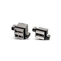
USB & Firewire Connectors USB PCB RECPT RA IP67 TYPE A DUAL
Manufacturer
Amphenol
Series
MUSBr
Datasheet
1.MUSBD11130.pdf
(3 pages)
Specifications of MUSB-C111-30
Product
USB Type A Connectors
Contact Plating
Gold
Contact Material
Phosphor Bronze
Current Rating
1.5 A
Mounting Style
Through Hole
Termination Style
Solder Tail
Color
Black
Insulation Resistance
1000 MOhms
Insulator Color
Black
Mounting Angle
Right
Number Of Positions / Contacts
4
Operating Temperature Range
- 40 C to + 105 C
Standard
USB
Gender
Female
Connector Type
USB Type A Receptacle, dual port, stacked
Number Of Ports
2
Voltage Rating
100 VDC
Lead Free Status / RoHS Status
Lead free / RoHS Compliant
Other names
01M3138, 720-3160


Amphenol Canada
605 Milner Avenue
Toronto, Ontario, Canada M1B 5X6
Telephone: 416-291-4401
Fax: 416-754-8668
www.amphenolcanada.com
MUSB Connector series designation - Rugged USB
Notes
1) Termination code 2 currently available for styles A, C & D. A 14 pin cable header is used for styles A & C. A 10 pin cable header is used for style D.
2) Termination code 3 currently available for styles A & C.
3) Termination code 4 currently available for style C using 2 x 5 position terminal blocks. Proposed for style A.
4) Termination code 6 proposed for style A only.
5) Termination code 8 proposed for style A & C
6) Termination Code B currently available for style A
7) Termination code D currently available for style C
8) Rear shield required for styles A, C, D, with right angle pcb tails. Rear shield optional for styles B & E with r/a pcb tails. No rear shield for any vertical
pcb tail.
9) Unified National thread - use #4-40 UNC for styles A, C, D, and #2-56 UNC for styles B & E.
10) Metric thread - use M3 for styles A, C, D, and M2 for styles B & E.
11) Unique special code defines the entire part. Note that code 3, for example, may have a completely different definition for every connector where it is
used.
A - Receptacle type A, single
B - Receptacle type Mini-B, single
C - Receptacle type A over type A, stacked
D - Receptacle type B, single
E - Receptacle type Mini-AB, single
TERMINATION
1 - Right angle pcb tail
2 - Right angle pcb tail, on pcb with right angle cable header, note 1
3 - Right angle pcb tail, on pcb with matching USB termination, note 2
4 - Right angle pcb tail, on pcb with terminal block(s), note 3
5 - Vertical pcb tail
6 - Right angle pcb tail, on pcb with MRJ & r/a cable header, note 5
8 - Right angle pcb tail, on pcb with vertical cable header, note 5
A - Right angle pcb tail, on pcb without extra connectors,note 4
B - Right angle pcb tail, on pcb vertical 5 pin one row header note 6
D - Right angle pcb tail, on pcb, vertical 2x5 dual row header note 7
NUMBER OF CONTACTS
1 - Standard 4 per port (use for styles A, C & D)
5 - Standard 5 per port (use for styles B & E)
COLOR
1 - Standard black
OPTIONS
0 - No rear shield; shell with Unified National thread, note 8 & 9
3 - With rear shield; shell with Unified National thread, note 8 & 9
M - With rear shield; shell with Metric thread, note 8 & 10
SPECIALS
0 - Standard (means 30u" (0.76um) gold, no dust cover)
1 - With grey color dust cover (supplied bulk packed)
3 - 50u" (1.27um) gold
5 - With black color dust cover (supplied bulk packed)
6 - Vertical with 4.6mm tail length - for MUSB-A511-06 only
UNIQUE SPECIAL CODE
No Digit - Part defined by previous 10 digits
1 to 9 - Unique special feature. Consult Factory
STYLE
or www.amphenolacp.com
MUSB CONNECTOR PRODUCT NUMBERING SYSTEM
Copyright © Amphenol Corporation 2006 • All rights reserved
MUSB - C
2
1
1
-
3
1
3
Related parts for MUSB-C111-30
Image
Part Number
Description
Manufacturer
Datasheet
Request
R

Part Number:
Description:
USB & Firewire Connectors USB PCB RECPT RA IP67 TYPE A SINGLE
Manufacturer:
Amphenol
Datasheet:

Part Number:
Description:
MINI USB INTERFACE
Manufacturer:
Samtec Inc
Datasheet:

Part Number:
Description:
DUST COVER FOR MUSB TYPE A BLACK
Manufacturer:
Amphenol Commercial Products
Datasheet:

Part Number:
Description:
CONN RCPT USB SGL STD W/O SHIELD
Manufacturer:
Amphenol Commercial Products
Datasheet:

Part Number:
Description:
CONN RCPT USB TO USB SGL STD
Manufacturer:
Amphenol Commercial Products
Datasheet:

Part Number:
Description:
Cable Specification: PU CABLE, UL20549 24AWG*8C+AD,OD= 6.0mm
Manufacturer:
Amphenol