Y92P-CXT4B Omron, Y92P-CXT4B Datasheet
Y92P-CXT4B
Specifications of Y92P-CXT4B


Related parts for Y92P-CXT4B


Y92P-CXT4B Summary of contents
Page 1
... Models with Screw Terminals 100 to 240-VAC / VDC Models with Screw Terminals Models with Sockets: 63.7 mm (case dimension) * The shortest body for a timer with isolated power supply and input circuits and a maximum ambient temperature of 55°C (according to OMRON investigation in June 2009). Previous New models models ...
Page 2
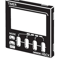
H5CX-@-N Other Features Change the Front Panel Color The Front Panel can be replaced with an optional Front Panel (order separately) with a different color to match the installation site. Select from black, white, and light gray. Black White (standard) ...
Page 3
Model Number Legend (Not all possible combinations of functions are available.) H5CX- @@@@@-N – – – – – Type Classifier Symbol Meaning A Standard type B 6-digit type L Economy type 4. Output type ...
Page 4
... Y92P-CXT4G Light gray (5Y7/1) Y92P-CXT4S White (5Y9.2 / 0.5) Y92P-CXT4B Black (N1.5) Note: 1. You can change the color of the front panel when mounting the Timer. The Timer is shipped with a black (N1.5) Front Panel. 2. "TIMER" is printed on the front of Replacement Front Panels. Soft Cover ...
Page 5
H5CX-A@-N/-L@-N Digital Timers • Switch the display color* between red, green, and orange to see the output status from a distance. • Up/Down Keys for each digit enable easy operation. • Cyclic control is easy with the Twin Timer and ...
Page 6
H5CX-A@-N/-L@-N Characteristics Power-ON start: ±0.01% ±50 ms max. (See note 1.) Signal start: ±0.005%±0.03 ms max. (See note 1.) Accuracy of operating time Signal start for transistor output model: ±0.005%±3 ms max. (See note and setting error (including 1 and ...
Page 7
... Immunity Burst: Immunity Surge: Immunity Voltage Dip/Interruption: *1. The following safety standards apply to models with sockets (H5CX-A11@ or H5CX-L8@). cUL (Listing): Applicable when an OMRON P2CF (-E) Socket is used. cUR (Recognition): Applicable when any other socket is used. *2. Excluding the H5CX-ASD-N/-A11SD-N/-L8SD-N. I/O Functions For details, refer to the timing charts on page 20 and page 29. ...
Page 8
H5CX-A@-N/-L@-N Connections Block Diagram (Basic insulation) Output circuit (Basic insulation) Internal control Input circuits circuit Note: Basic insulation is provided between the power supply circuit and the input circuits. However, basic insulation is not provided in the H5CX-@D-N. Terminal Arrangement ...
Page 9
Input Circuits Signal, Reset, and Gate Input No-voltage Inputs (NPN Inputs) Voltage Inputs (PNP Inputs) + kΩ Internal IN IN circuit Input Connections The inputs are no-voltage (closed or open) inputs or voltage inputs except for the H5CX-L8@. ...
Page 10
H5CX-A@-N/-L@-N Nomenclature Display Section 1. Key Protect Indicator (orange) 2. Control Output Indicator (orange) 3. Reset Indicator (orange) 4. Present Value Display (Main display) * (Character height: 12 mm, red ) * Characters on models with screw terminals (H5CX-A@) can ...
Page 11
Dimensions with Flush Mounting Adapter H5CX-A-N/-AS-N (Provided with Adapter and Waterproof Packing) Y92S-29 (provided) Waterproof Packing 58 48 H5CX-AD-N/-ASD-N (Provided with Adapter and Waterproof Packing) Y92S-29 (provided) Waterproof Packing 58 48 H5CX-A11@-N (Adapter and Waterproof Packing Ordered Separately) Y92S-29 (order ...
Page 12
... The Timer is shipped with a black (N1.5) Front Panel. Y92P-CXT4S Cover for Timer with 4 Digits White (5Y9.2/0.5) Y92P-CXT4G Cover for Timer with 4 Digits Light gray (5Y7/1) Y92P-CXT4B Cover for Timer with 4 Digits Black (N1.5) Replacement Method The Front Panel is attached to the Terminal with tabs in four locations. To remove the Front Panel, open the tabs and pull the Front Panel forward ...
Page 13
Connection Sockets Front-connecting Sockets Model P2CF-08 Two, 4.5-dia. holes Eight, M3.5 x 7.5 sems screws P2CF-08-E (Finger Safe Terminal) Two, 4.5-dia. holes Eight, M3.5 x 7.5 set screws P2CF-11 Two, 4.5-dia. holes Eleven, M3.5 x 7.5 sems screws P2CF-11-E (Finger ...
Page 14
H5CX-A@-N/-L@-N Terminal Covers for P3G-08 and P3GA-11 Back-connecting Sockets Model Y92A-48G Twelve, 6.4 dia 34 Y92A-48G Note: The Terminal Cover can be used with a Back-mounting Socket (P3G-08 or P3GA-11) to create a finger-safe construction. Optional Products for Track Mounting ...
Page 15
Operating Procedures Setting Procedure Guide * Settings for Timer Operation Use the following settings. Settings for Twin Timer Operation Refer to page 25 not necessary to mount the Waterproof Packing if waterproof construction is not required. Operating ...
Page 16
H5CX-A@-N/-L@-N Timer Step2 Settings that cannot be performed with the DIP switch are performed with the operation keys. • Change to Function Setting Mode. Power min. Run mode Function setting mode * ...
Page 17
From previous To previous page page Set the digits for the set value limit using the corresponding Set value upper limit 1 (1) Set the key protect level using the Key protect level kp-1 (KP-1) *1 Output ON count alarm ...
Page 18
H5CX-A@-N/-L@-N Timer Explanation of Functions Operating Procedures for Timer Function Items marked with stars ( ) can be set using the DIP switch. Time Range (timr) Set the range to be timed in the range 0.001 s to 9,999 h. ...
Page 19
Operation in Run Mode Operating Procedures for Timer Function Present value Set value When Output Mode Z Is Selected Present value ON duty ratio Present value Cycle time Present Value and Set Value These items are displayed when the power ...
Page 20
H5CX-A@-N/-L@-N Timer Timing Charts Operating Procedures for Timer Function Models without Instantaneous Contact Outputs The gate input is not included in the H5CX-L8@ models. Mode A: Signal ON delay 1 (Timer resets when power comes ON.) Basic operation Power * ...
Page 21
Mode b: Repeat cycle 1 (Timer resets when power comes ON.) Basic operation Power * Start signal input Timing Timing Timing Timing Output * Start signal input is disabled during timing. Timing starts when the start signal goes ON. The ...
Page 22
H5CX-A@-N/-L@-N Timer Mode d: Signal OFF delay (Timer resets when power comes ON.) Basic operation Power * Start signal input Timing Output * Start signal input is enabled during timing. The control output is ON when the start signal is ...
Page 23
Mode S: Stopwatch (Timer resets when power comes ON.) Basic operation Power Start signal input Timing Gate/Reset * Display (for elapsed * RST flashes time) The signal starts and stops timing. The display is held and timing is continued if ...
Page 24
H5CX-A@-N/-L@-N Timer Mode E: Interval (Timer resets when power comes ON.) Basic operation Power Timing Time-limit output Instantaneous output The Timer starts when the power comes ON or when the reset input goes OFF. Note: Output is not instantaneous when ...
Page 25
Setting Procedure Guide Operating Procedures for Twin Timer Function Step1 Switching to a Twin Timer Power ON Timer/twin timer selection mode + 1 Hold down for 1 s min. Run mode 1 + Hold down for 1 s min. Step2 ...
Page 26
H5CX-A@-N/-L@-N Twin Timer To switch to twin timer operation, use the procedure given below. For details, refer to page 31. Step3 Settings that cannot be performed with the DIP switch are performed with the operation keys. • Change to Function ...
Page 27
From previous To previous page page Set the digits for the set value limit using the corresponding Set value upper limit 1 1 (1) Set the digits for the set value limit using the corresponding Set value upper limit 2 ...
Page 28
H5CX-A@-N/-L@-N Twin Timer Explanation of Functions Operating Procedures for Twin Timer Function Items marked with stars ( ) can be set using the DIP switch. OFF Time Range (oftr) Set the time range for the OFF time in the range ...
Page 29
Timing Charts Operating Procedures for Timer Function Models without Instantaneous Contact Outputs The gate input is not included in the H5CX-L8@ models. Mode toff: Flicker OFF start 1 (Timer resets when power comes ON.) Basic operation Power * Start signal ...
Page 30
H5CX-A@-N/-L@-N Twin Timer Mode ton-1: Flicker ON start 2 (Timer does not reset when power comes ON.) Basic operation Power * Start signal input Timing Timing Timing a ON OFF ON Output ( OFF time) * Start ...
Page 31
Timer/Twin Timer Selection Mode (Function Selection) Select whether the H5CX is used as a timer or a twin timer in timer/twin timer selection mode. The H5CX is also equipped with a DIP switch monitor function, a convenient function that enables ...
Page 32
H5CX-A@-N/-L@-N Key Protect Level When the key-protect switch is set to ON possible to prevent setting errors by prohibiting the use of certain operation keys by specifying the key protect level (KP-1 to KP-7). The key protect indicator ...
Page 33
Digital Timer H5CX-B@-N • H5CX Digital Timers with 6-digit Display, 2-stage Setting, and Forecast Output (DIN 48 x 48-mm) • Times the daily operating hours of machinery and tools, predicting and notifying when maintenance is required. • Easy-to-read backlit negative ...
Page 34
H5CX-B@-N Characteristics Power-ON start: ±0.01% ±50 ms max. (See note 1.) Signal start: ±0.005%±0.03 ms max. (See note 1.) Accuracy of operating time Signal start for transistor output model: ±0.005%±3 ms max. (See note 1 and 2.) and setting error ...
Page 35
Connections Block Diagram Power supply Output circuit (Basic insulation) Internal control Input circuits circuit Terminal Arrangement Note: 1. The power supply and input circuit are not isolated. 2. Terminals 1 and 6 are ...
Page 36
H5CX-B@-N Nomenclature Display Section 1. Key Protection Indicator (orange) Lit when the reset input or Reset Key is ON. 2. Control Output Indicator (orange) Forecast value setting Forecast output ON: OUT 1 is lit. Control output ON: OUT 2 is ...
Page 37
Operating Procedures DIP Switch Settings All functions are set using the DIP switch. Item OFF ON 1 Refer to the table on the Time range right Output modes F-1 mode A mode 4 Input signal width 20 ms ...
Page 38
H5CX-B@-N Operation in Function Setting Mode Settings that cannot be performed with the DIP switch are performed with the operation keys. • Change to Function Setting Mode. Power min. Run mode Function setting mode *2 3 ...
Page 39
Explanation of Functions Absolute value setting/forecast value setting (setm) Set value 1 can be set as the forecast value setting ( abs absolute value setting ( ). Forecast Value Setting Present Example: F-1 Mode value Set value Forecast set value ...
Page 40
H5CX-B@-N Timing Charts Mode A: Signal ON delay (Timer resets when power comes ON.) Basic operation Power * Start signal input Timing Forecast ( Control ) output output 1 OUT1 OUT1 Control ( Control ) output output 2 OUT2 OUT2 ...
Page 41
Safety Precautions for All H5CX Series (Common) CAUTION Do not allow pieces of metal, wire clippings, or fine metallic shavings or fillings from installation to enter the product. Doing so may occasionally result in electric shock, fire, or malfunction. Minor ...
Page 42
H5CX-@-N Precautions for Correct Use • H5CX models with a 24-VDC/12 to 24-VDC power supply use a transformer-free power supply method in which the power supply terminals are not isolated from the signal input terminals non- isolating DC ...
Page 43
... Cancellation; Etc. Orders are not subject to rescheduling or cancellation unless Buyer indemnifies Omron against all related costs or expenses. 10. Force Majeure. Omron shall not be liable for any delay or failure in delivery resulting from causes beyond its control, including earthquakes, fires, floods, strikes or other labor disputes, shortage of labor or materials, accidents to machinery, acts of sabotage, riots, delay in or lack of transportation or the requirements of any government authority ...
Page 44
... OMRON ELECTRONICS LLC • THE AMERICAS HEADQUARTERS Schaumburg, IL USA • 847.843.7900 • 800.556.6766 • www.omron247.com OMRON CANADA, INC. • HEAD OFFICE Toronto, ON, Canada • 416.286.6465 • 866.986.6766 • www.omron.ca OMRON ELETRÔNICA DO BRASIL LTDA • HEAD OFFICE São Paulo, SP, Brasil • 55.11.2101.6300 • www.omron.com.br OMRON ELECTRONICS MEXICO • ...