TXD2SS-24V Panasonic, TXD2SS-24V Datasheet - Page 7
TXD2SS-24V
Manufacturer Part Number
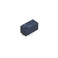
TXD2SS-24V
Description
Low Signal Relays - PCB 2 Form C 2A 30VDC 24VDC
Manufacturer
Panasonic
Datasheet
1.TXD2SS-12V-Z.pdf
(12 pages)
Specifications of TXD2SS-24V
Contact Form
2 Form C
Coil Voltage
24 VDC
Coil Current
9.6 mA
Coil Type
Single Side Stable
Power Consumption
230 mW
Contact Carry Current
2 A at 30 VDC
Termination Style
Solder Pad
Isolation
20 dB at 1 GHz
Insertion Loss
0.8 dB at 1 GHz
Maximum Switching Current
2 A
Contact Rating
2 A at 30 VDC
Lead Free Status / RoHS Status
Lead free / RoHS Compliant
Available stocks
Company
Part Number
Manufacturer
Quantity
Price
Company:

Part Number:
TXD2SS-24V
Manufacturer:
PANASONIC
Quantity:
12 000


2. Specifications
Notes: *1 M.B.B. type models are only available in 2,500 V surge breakdown voltage type.
Contact
Rating
Electrical
characteristics
Mechanical
characteristics
Expected life
Conditions
Unit weight
Characteristics
*2 This value can change due to the switching frequency, environmental conditions, and desired reliability level, therefore it is recommended to check this with the
*3 The upper operation ambient temperature limit is the maximum temperature that can satisfy the coil temperature rise value. Refer to [6] AMBIENT ENVIRONMENT
actual load. (AgPd contact type or SX relays are available for low level load switching [10V DC, 10mA max. level])
in GENERAL APPLICATION GUIDELINES.
Arrangement
Contact resistance (Initial)
Contact material
Nominal switching capacity
Max. switching power
Max. switching voltage
Max. switching current
Min. switching capacity (Reference value)*
Nominal operating
power
Insulation resistance (Initial)
Breakdown
voltage (Initial)
Surge breakdown
voltage (Initial)
Temperature rise (at 20°C 68°F)
Operate time [Set time] (at 20°C 68°F)
Release time [Reset time] (at 20°C 68°F)
Shock
resistance
Vibration
resistance
Mechanical
Electrical
Conditions for operation, transport and
storage*
Max. operating speed (at rated load)
3
Single side stable
1 coil latching
Between open contacts
Between contact and coil
Between contact sets
Between open contacts
Between contacts and
coil*
Functional
Destructive
Functional
Destructive
Item
All Rights Reserved © COPYRIGHT Panasonic Electric Works Co., Ltd.
1
2
1,000 Vrms for 1min. (Detection current: 10mA)
1,500 Vrms for 1min. (Detection current: 10mA)
2,000 Vrms for 1min. (Detection current: 10mA)
3,000 Vrms for 1min. (Detection current: 10mA)
Min. 1,000MΩ (at 500V DC) Measurement at same location as “Initial breakdown voltage” section.
Surge breakdown voltage 6,000 V and 6,000 V
Min. 5×10
200mW (1.5 to 12 V DC), 230mW (24 V DC)
280mW (1.5 to 12 V DC), 310mW (24 V DC)
150mW (1.5 to 12 V DC), 170mW (24 V DC)
230mW (1.5 to 12 V DC), 250mW (24 V DC)
Max. 4 ms [Max. 4 ms] (Nominal coil voltage applied to the coil, excluding contact bounce time.)
Max. 4 ms [Max. 4 ms] (Nominal coil voltage applied to the coil, excluding contact bounce time.)
AgPd contact: 1 A 30 V DC (resistive load)
Standard contact: 2 A, AgPd contact: 1 A
AgPd contact: 30 W (DC) (resistive load)
6,000 V (High breakdown voltage) types:
6,000 V (High breakdown voltage) type:
6,000 V (High breakdown voltage) type:
6,000 V (High breakdown voltage) type:
Surge breakdown voltage 2,500 V type:
Surge breakdown voltage 2,500 V type:
Surge breakdown voltage 6,000 V and
(Half-wave pulse of sine wave: 6 ms;
1,500 V (10×160µs) (FCC Part 68)
(High breakdown voltage) types:
Min. 10
Standard contact: 2 A 30 V DC,
Standard contact: 60 W (DC),
2,500 V, 2 × 10µs (Telcordia)
2,500 V and 6,000 V types:
2,500 V and 6,000 V types:
2,500 V and 6,000 V types:
5
Surge breakdown voltage
Surge breakdown voltage
Surge breakdown voltage
Surge breakdown voltage
Surge breakdown voltage
Surge breakdown voltage
(1 A 30 V DC resistive) (at 20 cpm)
Humidity: 5 to 85% R.H. (Not freezing and condensing at low temperature)
AgPd contact (low level load): AgPd+Au clad (stationary), AgPd (movable)
detection time: 10µs.)
Min. 10
6,000 V, 1.2 × 50µs
5
10 to 55 Hz at double amplitude of 3.3 mm (Detection time: 10µs.)
(2 A 30 V DC resistive),
Min. 750 m/s
220 V DC
Min. 1,000 m/s
2 Form C
(By resistive method, nominal coil voltage applied to the coil;
8
Ambient temperature: –40°C to +85°C
(at 180 cpm)
1,000 Vrms for 1min. (Detection current: 10mA)
Max. 100 mΩ (By voltage drop 6 V DC 1A)
contact carrying current: 2A [1A: M.B.B.].)
10 to 55 Hz at double amplitude of 5 mm
2
2
Standard contact: Ag+Au clad,
{100G} (Half-wave pulse of sine wave: 6 ms.)
Approx. 2 g
Max. 50°C
10µA10mV DC
(without diode)
Specifications
20 cpm
2,000 Vrms for 1min. (Detection current: 10mA)
.071 oz
122°F
500 Vrms for 1min. (Detection current: 10mA)
250mW (1.5 to 12 V DC), 270mW (24 V DC)
Min. 10
(Half-wave pulse of sine wave: 11 ms;
–40°F to
5
2,500 V, 2 × 10µs (Telcordia)
1 A 30 V DC (resistive load)
(1 A 30 V DC resistive) (at 20 cpm)
30 W (DC) (resistive load)
2 Form D (M.B.B.type)*
detection time: 10µs.)
Min. 10
Min. 500 m/s
+185°F;
110 V DC
7
(at 180 cpm)
1 A
—
—
2
1
TX-D
Related parts for TXD2SS-24V
Image
Part Number
Description
Manufacturer
Datasheet
Request
R

Part Number:
Description:
RELAY 2A 12VDC 200MW SMD
Manufacturer:
Panasonic Electric Works
Datasheet:
Part Number:
Description:
RELAY 2A 24VDC 230MW SMD
Manufacturer:
Panasonic Electric Works
Datasheet:
Part Number:
Description:
RELAY 2A 5VDC 200MW SMD
Manufacturer:
Panasonic Electric Works
Datasheet:
Part Number:
Description:
RELAY 2A 12VDC 200MW SMD
Manufacturer:
Panasonic Electric Works
Datasheet:
Part Number:
Description:
RELAY 2A 5VDC 200MW SMD
Manufacturer:
Panasonic Electric Works
Datasheet:

Part Number:
Description:
RELAY LATCH 2A 4.5VDC 150MW SMD
Manufacturer:
Panasonic Electric Works
Datasheet:
Part Number:
Description:
RELAY 2A 1.5VDC 200MW SMD
Manufacturer:
Panasonic Electric Works
Datasheet:
Part Number:
Description:
RELAY 2A 3VDC 200MW SMD
Manufacturer:
Panasonic Electric Works
Datasheet:
Part Number:
Description:
RELAY 2A 9VDC 200MW SMD
Manufacturer:
Panasonic Electric Works
Datasheet:
Part Number:
Description:
RELAY LATCH 2A 4.5VDC 150MW SMD
Manufacturer:
Panasonic Electric Works
Datasheet:

Part Number:
Description:
Color CCD Linear Image Sensor with 1024 Pixels for R and B Colors/2048 Pixels for G Color
Manufacturer:
Panasonic
Datasheet:
Part Number:
Description:
2048-Bit CCD Linear Image Sensor
Manufacturer:
Panasonic
Datasheet:
Part Number:
Description:
2592-Bit CCD Linear Image Sensor
Manufacturer:
Panasonic
Datasheet:
Part Number:
Description:
2048-Bit High-Responsivity CCD Linear Image Sensor with Internal Clock Driver
Manufacturer:
Panasonic
Datasheet: