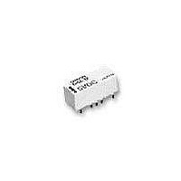
G6Z-1FE-DC5 Omron, G6Z-1FE-DC5 Datasheet

G6Z-1FE-DC5
Specifications of G6Z-1FE-DC5
Related parts for G6Z-1FE-DC5
G6Z-1FE-DC5 Summary of contents
Page 1
... None: Single-side stable U: Single-winding latching K: Double-winding latching 2. Contact Form 1: SPDT 3. Terminal Shape F: Surface-mounting terminals P: PCB terminals 118 4. Terminal Structure None: Y-shape terminal structure E: E-shape terminal structure 5. Characteristic Impedance None: 75 Ω Ω 6. Contact Arrangement None: Standard contact arrangement R: Reverse contact arrangement G6Z ...
Page 2
... VDC 50 Ω 12, and 24 VDC 75 Ω 12, and 24 VDC 50 Ω 12, and 24 VDC G6Z Model G6Z-1PE G6Z-1PE-A G6Z-1P G6Z-1P-A G6ZU-1PE G6ZU-1PE-A G6ZU-1P G6ZU-1P-A G6ZK-1PE G6ZK-1PE-A G6ZK-1P G6ZK-1P-A Model G6Z-1FE G6Z-1FE-A G6Z-1F G6Z-1F-A G6ZU-1FE G6ZU-1FE-A G6ZU-1F G6ZU-1F-A G6ZK-1FE G6ZK-1FE-A G6ZK-1F G6ZK-1F-A 119 ...
Page 3
... These values are for an impedance of 50 Ω Ω with a V.SWR of 1.2 max. 120 900 MHz TH SMD Y-shape E-shape Y-shape E-shape 60 dB min min min min min. 0.5 dB max. 0.3 dB max. 1.5 max. 1.3 max. 14.0 dB min. 17.7 dB min. G6Z 2.6 GHz TH SMD Y-shape E-shape Y-shape ...
Page 4
... Must operate voltage 75% max. of rated voltage Must release voltage 75% max. of rated voltage Maximum voltage 150% of rated voltage Power consumption Approx. 200 mW Double-winding Latching Models G6ZK-1P(E), G6ZK-1F(E) Raged voltage 3 VDC Rated current 120 mA Coil resistance 25 Ω Must operate voltage 75% max. of rated voltage Must release voltage 75% max ...
Page 5
... Electrical: 300,000 operations min. (30 VAC, 10 mA/30 VDC, 10 mA), 100,000 operations min. (900 MHz switching frequency of 1,800 operations/hour Operating: − 40 ° ° C (with no icing or condensation) Operating 85% Approx. 2.8 g Ambient Temperature vs. Must Operate or Must Release Voltage 100 Max. estimated value Sample: G6Z-1P 5 VDC 90 Number of relays: 5 max avg. min. 60 ...
Page 6
... Must release 20 0 0.0001 0.001 0.01 0 Operating frequency (×10 operations) Electrical Endurance (Contact Resistance) 1,000 NO Sample: G6Z-1PE 75 Ω 5 VDC 700 contact Number of Relays Test conditions resistive load 500 contact at 30 VDC Switching frequency: 1,800 operations/h 300 100 70 Contact resistance 50 max. max. ...
Page 7
... Sample: G6Z-1P 75 Ω 5 VDC 20 Number of Relays 0.5 1.0 1.5 2.0 Time (ms) G6Z High-frequency Characteristics at 75 Ω (Return Loss, V.SWR) (See notes 1 and 2.) (Average value (initial value)) 0 Sample: G6Z-1PE 75 Ω 5 VDC with terminating resistance 10 Return loss V.SWR 50 60 N.O. N. 500 1,000 1,500 2,000 ...
Page 8
... Mounting Dimensions (Bottom View) Tolerance: ±0.1 mm Nine, 1.8-dia. Nine, 1.0-dia. holes 7.62 2.54 7.62 15.24 0.18 G6Z Terminal Arrangement/Internal Connections (Bottom View) G6Z-1PE Orientation mark − G6ZU-1PE Orientation mark − − G6Z-1PE-R Orientation mark − Terminal Arrangement/Internal ...
Page 9
... Eleven, 1.0-dia. holes 7.62 2.54 7.62 15.24 0.18 Mounting Dimensions (Bottom View) Tolerance: ±0.1 mm Seven, 1.8-dia. Seven, 1.0-dia. holes 7.62 Three, 1.6-dia. Three, 0.8-dia. holes 2.54 7.62 15.24 0.18 G6Z Terminal Arrangement/Internal Connections (Bottom View) G6Z-1P Orientation mark − G6ZU-1P Orientation mark − ...
Page 10
... Nine, 1.8-dia. Nine, 1.0-dia. holes 7.62 Three, 1.6-dia. Three, 0.8-dia. holes 2.54 7.62 15.24 0.18 Mounting Dimensions (Bottom View) Tolerance: ±0.1 mm Twelve, 1.8-dia. Twelve, 1.0-dia. holes. 7.62 2.54 7.62 15.24 0.18 G6Z Terminal Arrangement/Internal Connections (Bottom View) Orientation mark − − ...
Page 11
... Mounting Dimensions (Top View) Tolerance: ±0.1 mm 15.24 2.54 2.3 0.8 0.8 8.3 Eight, 1.1 0.8 7.62 0.18 G6Z Terminal Arrangement/Internal Connections (Top View) G6Z-1FE Orientation mark − G6ZU-1FE Orientation mark − − Terminal Arrangement/Internal Connections (Top View) G6Z-1FE-A Orientation mark − ...
Page 12
... Mounting Dimensions (Top View) Tolerance: ±0.1 mm 15.24 7.62 2.54 2.3 0.8 0.8 0.8 8.3 0.18 Seven, 1.1 Mounting Dimensions (Top View) Tolerance: ±0.1 mm 15.24 7.62 2.3 2.54 8.3 Ten, 1.1 0.18 G6Z Terminal Arrangement/Internal Connections (Top View) G6Z-1F-A Orientation mark − G6ZU-1F-A Orientation mark 14 ...
Page 13
... Mounting Dimensions (Top View) Tolerance: ±0.1 mm 15.24 7.62 2.54 2.3 0.8 0.8 8.3 0.18 Nine, 1.1 0.8 Mounting Dimensions (Top View) Tolerance: ±0.1 mm 15.24 7.62 2.3 2.54 8.3 Twelve, 1.1 0.18 G6Z Terminal Arrangement/Internal Connections (Top View) Orientation mark − − ...
Page 14
... A + 0.1 1 0.15 1.7 0 0.2 R0.75 Enlarged view of A Incorrect Soldering Insufficient amount of Solder solder Land G6Z 21 dia. ±0 ±0.1 Excessive amount of solder 131 ...
Page 15
... Please observe the following precautions to prevent failure to operate, malfunction, or undesirable effect on product perfor- mance. High-frequency Characteristics Measurement Method and Measurement Substrate High-frequency characteristics for the G6Z are measured in the way shown below. Consult your OMRON representative for details on 50- Ω models. Measurement Method for 75- Ω Models G6Z ...
Page 16
... Be sure to apply a reset signal before use. Coating Do not use silicone coating to coat the Relay when it is mounted to the PCB. Do not wash the PCB after the Relay is mounted using detergent containing silicone. Otherwise, the detergent may remain on the surface of the Relay. G6Z 133 ...


