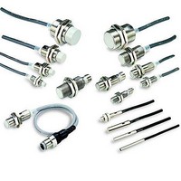
E2EQ-X7D1-M1GJ Omron, E2EQ-X7D1-M1GJ Datasheet - Page 5

E2EQ-X7D1-M1GJ
Manufacturer Part Number
E2EQ-X7D1-M1GJ
Description
Proximity Sensors With M12 Pigtail 1&4
Manufacturer
Omron
Type
Inductive Proximity Sensorr
Series
E2EQr
Specifications of E2EQ-X7D1-M1GJ
Maximum Operating Temperature
+ 70 C
Supply Voltage
24 V
Operating Supply Voltage
10 V to 30 V
Minimum Operating Temperature
- 25 C
Maximum Output Current
100 mA
Barrel Size
M18
Features
NO
Sensing Distance
7 mm
Sensor Type
Inductive
Sensing Object
Metallic
Response Frequency
500Hz
Material - Body
Fluoroplastic Coated Brass
Shielding
Shielded
Voltage - Supply
10 V ~ 30 V
Output Type
NPN-NO
Terminal Type
Connector
Package / Case
Cylinder, Threaded - M18
Lead Free Status / RoHS Status
Lead free / RoHS Compliant
Residual Output Voltage
E2EQ-X@X@(-M1J)
I/O Circuit Diagrams
Long Sensing-distance Models
Standard Models
E2EQ-X4X1
E2EQ-X8X1
E2EQ-X15X1
E2EQ-X4X1-M1J
E2EQ-X8X1-M1J
E2EQ-X15X1-M1J
E2EQ-X3D1
E2EQ-X7D1
E2EQ-X10D1
E2EQ-X3D1-M1GJ
E2EQ-X7D1-M1GJ
E2EQ-X10D1-M1GJ
5
4
3
2
1
0
1
Model
Model
3
5
10
Opera-
Opera-
mode
mode
tion
tion
NO
NO
Load current (mA)
30
(%)
Sensing
object
50
(%)
Non-sensing area
Sensing
object
Non-sensing area
100
distance
sensing
Rated
sensing
distance
Rated
E2EQ-X@D@(-M1GJ)
Unstable
sensing
area
Unstable
sensing
area
100
5
4
3
2
1
0
100
1
80 (TYP)
Timing Chart
Timing Chart
80 (TYP)
Set position
Stable sensing area
Set position
3
Stable sensing area
5
10
30
0
0
ON
OFF
ON
OFF
ON
OFF
50
ON
OFF
ON
OFF
ON
OFF
Proximity Sensor
100
Setting indicator
(green)
Operation indicator
(red)
Control output
Setting indicator
(green)
Operation
indicator (red)
Control output
Load current (mA)
300
500
1,000
Leakage Current
E2EQ-X@D
Note 1. The load can be connected to either the +V or
Note 2. There is no polarity. Therefore, the brown and
Note: The load can be connected to either the +V
Proximity
Sensor
Proximity
1.5
1.0
0.5
circuit
Sensor
main
circuit
main
0
or 0 V side.
0 V side.
blue lines have no polarity.
Note: Pins 2 and 3 are not used.
Note: Pins 1 and 2 are not used.
Connector Pin Arrangement
Connector Pin Arrangement
10
Output circuit
Output circuit
2
2
E2EQ-X7D1
1
3
1
3
4
20
4
Power supply voltage (V)
4
3
Brown
Blue
1
4
Brown
Blue
E2EQ-X10D1
Load
E2EQ-X3D1
Load
30
E2EQ
+V
0 V
0 V
+V
40
5


