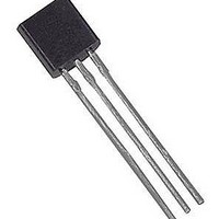
DS18S20+PAR Maxim Integrated Products, DS18S20+PAR Datasheet - Page 9

DS18S20+PAR
Manufacturer Part Number
DS18S20+PAR
Description
Board Mount Temperature Sensors PARASITE POW DIG THERMOMETER 1-WR
Manufacturer
Maxim Integrated Products
Specifications of DS18S20+PAR
Full Temp Accuracy
+/- 0.5 C
Package / Case
TO-92
Digital Output - Bus Interface
Serial (1-Wire)
Digital Output - Number Of Bits
9 bit
Maximum Operating Temperature
+ 100 C
Minimum Operating Temperature
- 55 C
Output Type
Digital
Ic Output Type
Digital
Sensing Accuracy Range
± 0.5°C
Supply Current
1mA
Supply Voltage Range
3V To 5.5V
Resolution (bits)
9bit
Sensor Case Style
TO-92
No. Of Pins
3
Accuracy %
0.5°C
Rohs Compliant
Yes
Lead Free Status / RoHS Status
Lead free / RoHS Compliant
1-WIRE BUS SYSTEM
The 1-Wire bus system uses a single bus master to control one or more slave devices. The DS18S20 is
always a slave. When there is only one slave on the bus, the system is referred to as a “single-drop”
system; the system is “multidrop” if there are multiple slaves on the bus.
All data and commands are transmitted least significant bit first over the 1-Wire bus.
The following discussion of the 1-Wire bus system is broken down into three topics: hardware
configuration, transaction sequence, and 1-Wire signaling (signal types and timing).
HARDWARE CONFIGURATION
The 1-Wire bus has by definition only a single data line. Each device (master or slave) interfaces to the
data line via an open drain or 3-state port. This allows each device to “release” the data line when the
device is not transmitting data so the bus is available for use by another device. The 1-Wire port of the
DS18S20 (the DQ pin) is open drain with an internal circuit equivalent to that shown in Figure 9.
The 1-Wire bus requires an external pullup resistor of approximately 5kΩ; thus, the idle state for the
1-Wire bus is high. If for any reason a transaction needs to be suspended, the bus MUST be left in the idle
state if the transaction is to resume. Infinite recovery time can occur between bits so long as the 1-Wire
bus is in the inactive (high) state during the recovery period. If the bus is held low for more than 480µs,
all components on the bus will be reset.
Figure 9. Hardware Configuration
Tx
Rx
V
PU
4.7k
Tx = TRANSMIT
Rx = RECEIVE
1-Wire BUS
9 of 23
DQ
PIN
TYP
5μA
DS18S20 1-Wire PORT
MOSFET
100Ω
TX
Rx
DS18S20


