UCE-3.3/15-D48N-C Murata Power Solutions Inc, UCE-3.3/15-D48N-C Datasheet - Page 12
UCE-3.3/15-D48N-C
Manufacturer Part Number
UCE-3.3/15-D48N-C
Description
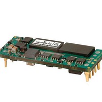
DC/DC Converters & Regulators 48Vin 3.3Vout 15A 49.5W Neg polarity
Manufacturer
Murata Power Solutions Inc
Specifications of UCE-3.3/15-D48N-C
Output Power
50 W
Input Voltage Range
36 V to 75 V
Input Voltage (nominal)
48 V
Number Of Outputs
1
Output Voltage (channel 1)
3.3 V
Output Current (channel 1)
15 A
Isolation Voltage
2.25 KV
Package / Case Size
Eighth Brick
Output Voltage
3.3 V
Product
Isolated
Dc / Dc Converter O/p Type
Eighth-Brick
No. Of Outputs
1
Input Voltage
36V To 75V
Power Rating
49.5W
Output Current
15A
Approval Bodies
CAN / CSA / EN / IEC / UL
Rohs Compliant
Yes
Lead Free Status / RoHS Status
Lead free / RoHS Compliant


Remote On/Off Control
On the input side, a remote On/Off Control can be specifi ed with either positive
or negative logic polarity.
pin is left open or is pulled high to +Vin with respect to –Vin. An internal bias
current causes the open pin to rise to approximately +15V. Some models will
also turn on at lower intermediate voltages (see Specifi cations). Positive-polarity
devices are disabled when the On/Off is grounded or brought to within a low
voltage (see Specifi cations) with respect to –Vin.
grounded or brought to within a low voltage (see Specifi cations) with respect to
–Vin. The device is off (disabled) when the On/Off is left open or is pulled high
to approximately +15V with respect to –Vin.
fi ed signal current when brought low and withstand appropriate voltage
when brought high. Be aware too that there is a fi nite time in milliseconds
(see Specifi cations) between the time of On/Off Control activation and stable,
regulated output. This time will vary slightly with output load type and current
and input conditions.
On/Off Enable Control Ground Bounce Protection
To improve reliability, if you use a small signal transistor or other external
circuit to select the Remote On/Off control, make sure to return the LO side
directly to the –Vin power input on the DC/DC converter. To avoid ground
bounce errors, do not connect the On/Off return to a distant ground plane or
Do not connect
control transistor
through remote
power bus
Positive: Models equipped with positive logic are enabled when the On/Off
Negative: Models with negative polarity are on (enabled) when the On/Off is
Dynamic control of the On/Off function should be able to sink the speci-
On/Off
Control
Transistor
Figure 9. On/Off Enable Control Ground Bounce Protection
Ground plane or power return bus
Preferred location
of On/Off control
adjacent to -Vin
terminal
Install separate
return wire for
On/Off control
with remote
transistor
DC/DC Converter
www.murata-ps.com
+ Vin
On/Off Enable
-Vin return
current-carrying bus. If necessary, run a separate small return wire directly to
the –Vin terminal. There is very little current (typically 1-5 mA) on the On/Off
control however, large current changes on a return ground plane or ground bus
can accidentally trigger the converter on or off. If possible, mount the On/Off
transistor or other control circuit adjacent to the converter.
you carefully observe the voltage levels, the preferred circuit is either an open
drain/open collector transistor, a switch or a relay (which can thereupon be
controlled by logic) returned to negative Vin.
power voltage. Otherwise the converter may be permanently damaged.
Output Capacitive Load
These converters do not require external capacitance added to achieve rated
specifi cations. Users should only consider adding capacitance to reduce switch-
ing noise and/or to handle spike current step loads. Install only enough capaci-
tance to achieve noise objectives. Excess external capacitance may cause
regulation problems, slower transient response and possible instability. Proper
wiring of the Sense inputs will improve these factors under capacitive load.
capacitor installed immediately adjacent to the converter. Any extended output
wiring or smaller wire gauge or less ground plane may tolerate somewhat higher
capacitance. Also, capacitors with higher ESR may use a larger capacitance.
There are two CAUTIONs for the On/Off Control:
CAUTION: While it is possible to control the On/Off with external logic if
CAUTION: Do not apply voltages to the On/Off pin when there is no input
The maximum rated output capacitance and ESR specifi cation is given for a
Isolated, High-Density, Eighth-Brick
Low Profi le DC/DC Converters
21 Feb 2011
email: sales@murata-ps.com
UCE Series
MDC_UCE.A30 Page 12 of 17
Related parts for UCE-3.3/15-D48N-C
Image
Part Number
Description
Manufacturer
Datasheet
Request
R

Part Number:
Description:
CONV DC/DC 49.5W 3.3V 15A
Manufacturer:
Murata Power Solutions Inc
Datasheet:

Part Number:
Description:
DC/DC Converters & Regulators 48Vin 3.3Vout 15A 49.5W W/Baseplate
Manufacturer:
Murata Power Solutions Inc
Datasheet:
Part Number:
Description:
DC/DC Converters & Regulators 48Vin 3.3Vout 15A 49.5W Pos polarity
Manufacturer:
Murata Power Solutions Inc
Datasheet:

Part Number:
Description:
CONV DC/DC 99W 3.3V 30A
Manufacturer:
Murata Power Solutions Inc
Datasheet:
Part Number:
Description:
DC/DC Converters & Regulators 48Vin 3.3Vout 30A 99W Neg polarity
Manufacturer:
Murata Power Solutions Inc
Datasheet:
Part Number:
Description:
DC/DC Converters & Regulators 48Vin 3.3Vout 30A 99W Pos polarity
Manufacturer:
Murata Power Solutions Inc
Datasheet:
Part Number:
Description:
DC/DC Converters & Regulators 48Vin 3.3Vout 30A 99W W/Baseplate
Manufacturer:
Murata Power Solutions Inc
Datasheet:

Part Number:
Description:
POWER OVER ETHERNET MODULE
Manufacturer:
Murata Power Solutions Inc
Datasheet:

Part Number:
Description:
POWER OVER ETHERNET MODULE
Manufacturer:
Murata Power Solutions Inc
Datasheet:

Part Number:
Description:
Transformers 5Vin 5Vout 200mA 4000Vdc 1:1.33 turn
Manufacturer:
Murata Power Solutions Inc
Datasheet:

Part Number:
Description:
POWER SUPPLY
Manufacturer:
Murata Power Solutions Inc
Datasheet:

Part Number:
Description:
DPM LED MINI 2VDC 3.5DIG LP RED
Manufacturer:
Murata Power Solutions Inc
Datasheet:

Part Number:
Description:
CONV DC/DC 1W 5VIN 5VOUT SIP SGL
Manufacturer:
Murata Power Solutions Inc
Datasheet:

Part Number:
Description:
CONV DC/DC 1W 5VIN 3.3V SIP SGL
Manufacturer:
Murata Power Solutions Inc
Datasheet: