DMS-30LCD-0-5B-C Murata Power Solutions Inc, DMS-30LCD-0-5B-C Datasheet - Page 3
DMS-30LCD-0-5B-C
Manufacturer Part Number
DMS-30LCD-0-5B-C
Description
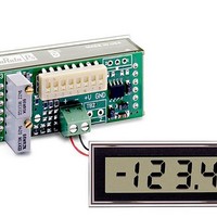
Digital Panel Meters 3.5 Digit Volt Meter +-200mV / +5VBacklit
Manufacturer
Murata Power Solutions Inc
Type
LCD Display Digital Panel Voltmetersr
Datasheet
1.DMS-30LCD-1-9-C.pdf
(6 pages)
Specifications of DMS-30LCD-0-5B-C
Equipment Type
LCD Display Digital Panel Voltmeters
Input
+/- 200 mV
Display Type
3 - 1/2 Digit LCD
Lead Free Status / RoHS Status
Lead free / RoHS Compliant
Other names
DMS-30LCD-0-5B-C
Available stocks
Company
Part Number
Manufacturer
Quantity
Price


3. Decimal Point Placement: The location of the decimal point is user-
4. REFERENCE OUTPUT (Pin 8) and INPUT (Pin 7): Pin 8 is a preci-
5. DISPLAY TEST (Pin 2): (Not available on backlit models)
6. BACKLIGHT (Pin 2) Function: For backlit models, grounding pin 2
7. Gain Adjust: There is a gain-adjust potentiometer on the back of each
selectable, and the decimal point control pins (DP1-DP3) are active low
functions. Select the appropriate decimal point by tying the appropriate
pin (pin 4, 5 or 6) to pin 3 (5V RETURN/
–BATTERY). Unused decimal point location pins should be left open.
For 5V-powered models, the decimal location pins are TTL compatible
and may be hard wired as described above or driven with 5V TTL logic
gates.
sion reference actively trimmed at the factory. In normal operation, pin
8 must be tied to pin 7 to achieve all listed accuracy and drift specifi ca-
tions.
(pin 1) to activate. All LCD segments, exclusive of the decimal points,
will be momentarily enabled. Do not leave the unit in the TEST
mode for more than 10 seconds as this will damage the LCD seg-
ments.
(i.e. connecting it to pin 3) turns on the backlighting LED’s. 9V-pow-
ered backlit models function with supply voltages up to +14V, however,
activating the backlight with voltages greater than 9.2V can damage
the meter. Therefore, a 1/4 Watt series resistor must be installed
between pins 3 and 2 in these situations. The value of the series resis-
tor is determined using the following formula:
Connect DISPLAY TEST (pin 2) to +5V SUPPLY/+BATTERY
In any backlit application, including those with supply voltages
drawn by the meter) can be reduced by installing a 1/4 Watt resistor
between pins 3 and 2. The brightness of the backlight will be reduced
proportionately.
meter. It has approximately ±50 counts (±2.5%) of adjustment range.
Since these devices essentially have no zero/offset errors, a gain
adjustment is effectively an overall accuracy adjustment. Though they
may be performed at any point (except zero), accuracy adjustments
are most effective when performed with higher level input signals.
Refer to Figure 9 for applications requiring greater ( ±10%) gain adjust-
ments.
< 9.2V, the current drawn by the backlight (and therefore the current
R
R
R
Example: If +BATTERY (pin 1 with respect to pin 3) is +12.6V,
Series
Series
Series
= 97 Ohms
=
=
+BATTERY – 9.2V
+12.6 – 9.2V
0.035
0.035
Ohms
Ohms
www.murata-ps.com/dpm
8. Soldering Methods: All models in the DMS-30LCD Series easily
9. Suggested Mating Connectors:
DMS-30LCD meters are available in either 5V-powered or 9V-powered
models. 9V devices operate directly from 7.5V to 14V supplies (usually
batteries) without the need for external voltage regulators. 9V devices,
however, can not be used to measure voltages referenced to the negative
battery terminal (pin 3) because the minus input to the meter (pin 12, (–)
INPUT LO) must always be at least 1.5V above pin 3. 9V-powered meters
can only be used to make differential and not single-ended measurements.
5V-powered devices operate from any well-regulated +5V supply and will
accurately measure voltages both above and below pin 3 (5V RETURN) in
either single-ended or differential confi gurations.
1. Single-Ended Input Confi gurations: True single-ended measure-
APPLICATIONS
withstand most common wave soldering operations. We recommend,
however, you evaluate the effects your particular soldering techniques
may have on the meter’s plastic case and high-precision electrical
performance. We recommend the use of no-clean lead-free solders.
Panel mounted:
Connector housing
Terminal type
Wire size
Insulation diameter
Stripping length
Board mounted:
Socket
ments can only be made with 5V-powered meters. The circuit of Figure
2 avoids problems normally associated with ground-loop currents.
Separate ground runs should be used for 5V RETURN (pin 3) and (–)
INPUT LO (pin 12).
120 VAC
+
–
V
3½ Digit, LCD Display Digital Panel Voltmeters
IN
AC to DC Converter
Figure 2. Single-Ended Input Confi guration
(–) IN LO
(+) IN HI
11
12
DMS-30LCD Series
+5V SUP
(5V-Powered Models)
06 Jan 2011 MPM_DMS30LCD.D02 Page 3 of 6
1
DATEL P/N 4320-01069-0
DATEL P/N 4400-01032-0
22 to 26 AWG
0.062” (1.57mm) maximum
0.100 to 0.125” (2.54 to 3.17mm)
DATEL P/N 4320-01074-0
DMS-30LCD-1-5
email: sales@murata-ps.com
6
DP1
3
5V RET
7
8
REF OUT
REF IN