FEATURES
■
■
■
■
■
■
www.murata-ps.com
TB1
Measure and accurately display dc voltages in harsh
environments
Four input ranges: ±200mVdc, ±2Vdc, ±20Vdc, and
±200Vdc
Daylight-readable LED display with automatic
brightness adjustment
Moisture & impact resistant package offers
NEMA-4/IP65 protection
Operates from universal 85-264Vac mains, or
110-300Vdc supplies
Input circuit fully isolated from ac power supply
Fused 85-264Vac
Power Source
1
Figure 1. DMU-30DCV wiring diagram
2
CAL
www.murata-ps.com/rohs
For full details go to
REAR VIEW
BRIGHTNESS
ADJUST
Input Signal
1
2
TB2
www.murata-ps.com/dpm
TECHNICAL NOTES
voltmeters measure and display dc signals as low as ±200mV and as high as ±200V. Their
large 0.56” (14.2mm) high super-bright red LED-display is readable in full sunlight. An
auto-dimming circuit automatically adjusts the display brightness for all viewing conditions.
plastic housing that features an integrated bezel and gasket assembly. In a typical instal-
lation, the housing is secured to a panel with six metallic threaded inserts, allowing the
unit to meet NEMA-4 / IP65 requirements for moisture and impact resistance in outdoor
applications.
±200mVdc (with 0.1mV resolution); ±2Vdc (0.001V resolution); ±20Vdc (0.01V resolution);
and ±200Vdc (0.1V resolution). The dc signal under measurement is electrically isolated
from the unit’s operating power source.
high-reliability instrumentation, alternative power generators, and any other application
which requires daylight readability and precise monitoring of dc voltages in harsh indoor /
outdoor environments. Simply connect the input signal and an 85-264Vac source of operat-
ing power to the two rear-mounted terminal blocks and the unit is fully operational.
IMPORTANT! To ensure safe and reliable operation, DMU-30DCV dc voltmeters must
be installed and serviced by qualifi ed technical personnel. Contact Murata / DATEL if
there is any doubt regarding installation and/or operation.
1. Measurement Type: All DMU-30DCV series dc voltmeters achieve their excellent
2. Wiring: All ac supply (TB1) and input signal (TB2) wiring must be adequately rated for
3. Power Supply Polarity, Fusing, Wiring and Grounding: The power supply inputs (TB1-1 and
performance by employing a precision integrating analog-to-digital converter, metal fi lm
resistor dividers, and a high-stability voltage reference IC. The LED display is updated
approximately 2.5 to 3 times per second. However, while some input fi ltering is provided,
noisy signals may cause the displayed reading to vary by a few counts.
the voltages and currents they will carry, and must comply with any code or application-
mandated requirements pertaining to the user’s specifi c installation.
TB1-2) on DMU-30DCV voltmeters are not polarity sensitive, that is, they have no “AC LO”
or “AC HI” designations. These units do not include or require a connection to earth/chas-
sis ground. Refer to Figure 1 for a typical wiring diagram.
Wires specifi ed in the Functional Specifi cations section must be used for making connec-
tions to DMU-30DCV series voltmeters. All power-supply and load wiring must be rated
for the supply voltages and currents they will conduct and must comply with any code or
application-mandated requirements pertaining to the user’s specifi c installation.
DMU-30DCV voltmeters are not internally fused. Terminal block TB1 is to be used only
for powering the power meter’s internal circuitry; it must not be used to supply power
to external loads. The supply wires feeding these power meters must be fused with a
0.5A/250V time delay/time lag fuse, in accordance with applicable regulatory codes.
Wire insulation must be stripped to within ±10% of the stated dimensions, and wires
should be inserted into TB1 such that their insulation is not pinched by the screw terminal.
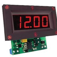
Murata Power Solutions’ DATEL branded DMU-30DCV series of daylight-readable dc
DMU-30DCV series dc voltmeters are packaged in a rugged, one-piece polycarbonate
DMU-30DCV series dc voltmeters are available in a choice of four input ranges:
DMU-30DCV series’ miniature size and rugged package are perfect for industrial and
Ruggedized DC Voltmeters with Daylight Readable
DMU-30DCV Series
24 Mar 2011 MPM_DMU_30DCV.A07 Page 1 of 3
Auto-Dimming LED Displays
email: sales@murata-ps.com