C146 10F016 003 1 Amphenol, C146 10F016 003 1 Datasheet - Page 185
C146 10F016 003 1
Manufacturer Part Number
C146 10F016 003 1
Description
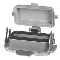
Heavy Duty Power Connectors BH HOUSING SNGL CLMP SP COVR 40CONT INSRT
Manufacturer
Amphenol
Series
C146 Seriesr
Datasheet
1.C146_10F003_000_4.pdf
(212 pages)
Specifications of C146 10F016 003 1
Housing Material
Aluminum, Diecast Alloy
Hood Orientation
Vertical
Number Of Positions / Contacts
16
Product Type
Housings
Termination Style
Screw
Lead Free Status / RoHS Status
Lead free / RoHS Compliant


Amphenol
C 146
Technische Informationen
Technical information
Strombelastbarkeit
Die Strombelastbarkeit eines Steckverbinders wird mit einer Derating-
Kurve dargestellt. Aus ihr kann abgelesen werden, welche Ströme
dauernd und gleichzeitig über alle Kontakte fließen dürfen. Die Kurve
wird durch Prüfung ermittelt. Als Basis dient dazu die Norm DIN EN
60512. Die obere Grenztemperatur wird durch die verwendeten Kontakt-
und Isolier werkstoffe bestimmt. Die Summe aus der
Umgebungstemperatur und der durch die Strombelastung
hervorgerufenen Übertemperatur darf die obere Grenztemperatur des
Steckverbinders nicht übersteigen. Somit ist die Strombelastbarkeit kein
konstanter Wert, sondern sinkt mit steigender Umgebungstemperatur.
Als allgemeines Beispiel sei gesagt, dass bei einem vorgegebenen
Steckverbinder, der bei einer Umgebungstemperatur von 40°C mit einem
Dauerstrom von 16A auf allen Kontakten belastet werden darf, dieser
Wert bei einer Umgebungstemperatur von 80°C auf z.B. 12A sinken
kann. Auf der anderen Seite ist es in der Praxis sehr oft der Fall, dass
nicht alle Anschlüsse gleichzeitig mit dem maximal zulässigen Strom
belastet werden, so dass dann einzelne Kontakte mit einem höheren
Strom als nach der Derating-Kurve zulässig, beaufschlagt werden
können. Diese Grenzwerte sind durch Prüfung zu ermitteln.
Diagramm 3
Tabelle 5
Strombelastbarkeit von Kupferleitern in (A)
Darstellung in Anlehnung an DIN EN 60204 für PVC-isolierte Kupferleiter in
einer Umgebungstemperatur von +40°C unter Dauerbetriebsbedingungen.
Für abweichende Bedingungen wie andere Temperaturen, Installationen,
Isoliermaterialien oder Leitern sind entsprechende Korrekturfaktoren zu
verwenden (siehe nächste Seite).
Installationsart
Installation type
B1 Leiter in Schutzrohren und Installationskanälen
B2 Kabel und Leitungen in Schutzrohren oder Installationskanälen
Wires in conduits and installation channels
Cables and conductors in conduits or installation channels
C Kabel und Leitungen an Wänden
E Kabel und Leitungen auf Kabelpritschen
Cables and conductors on plank
Cables and conductors along walls
Umgebungstemperatur
Typische Derating-Kurve
Durch die Werkstoffe gegebene
obere Grenztemperatur
Querschnitt (mm
Wire size (mm
2
)
2
)
0,25
-
-
4,0
4,0
Current carrying capacity
The current carrying capacity of a connector is shown by a derating
curve. The curve shows the currents that the connector can carry
continuously and simultaneously through all its contacts. The curve is
determined by testing following the standard DIN EN 60512. The upper
temperature is limited by the contact and insulation material used . The
sum of the ambient temperature and the temperature created by the
current flow may not exceed the upper temperature. This means that the
current carrying capacity has no fixed value but decreases with
increasing ambient temperatures.
As a general example it can be said that a given connector which can
carry 16A through all its contacts at 40°C ambient temperature can
carry less, e.g. 12A, at an ambient temperature of 80°C.
On the other hand it is often the case that not all contacts carry the
whole rated current, which means that some single contacts may carry a
higher current than that according to the derating curve. These currents
have to be defined by testing.
Diagram 3
Chart 5
Current carrying capacity of copper wires in (A)
Description according to DIN EN 60204 for PVC insulated copper wires with
a working temperature of +40C. For other requirements, such as for other
temperatures, mountings, or wires corresponding correction factors are
used (see next page).
0,34 0,5
-
-
5,0
5,0
-
-
7,1
7,1
7,6
-
9,1
9,1
0,75
Ambient temperature (°C)
Typical derating curve
1
10,4
9,6
11,7
11,5
Upper temperature limited
by the connector materials
1,5
13,5
12
15,2
16,1
2,5
18,3
16,5
21
22
4
25
23
28
30
6
32
29
36
37
10
44
40
50
52
185
Related parts for C146 10F016 003 1
Image
Part Number
Description
Manufacturer
Datasheet
Request
R

Part Number:
Description:
Heavy Duty Power Connectors PIN MODUL 10 WAY
Manufacturer:
Amphenol

Part Number:
Description:
Heavy Duty Power Connectors SOCKET MODULE 10 WAY
Manufacturer:
Amphenol

Part Number:
Description:
Heavy Duty Power Connectors PIN CONNECTOR 10 WAY
Manufacturer:
Amphenol

Part Number:
Description:
Heavy Duty Power Connectors FEMALE CONNECTOR 10 WAY
Manufacturer:
Amphenol

Part Number:
Description:
Cable Specification: PU CABLE, UL20549 24AWG*8C+AD,OD= 6.0mm
Manufacturer:
Amphenol