SDR1305-100M Bourns Inc., SDR1305-100M Datasheet
SDR1305-100M
Manufacturer Part Number
SDR1305-100M
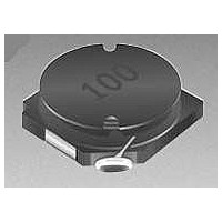
Description
INDUCTOR POWER 1305
Manufacturer
Bourns Inc.
Series
SDR1305r
Datasheet
1.SDR1305-102K.pdf
(2 pages)
Specifications of SDR1305-100M
Inductance
10 uH
Tolerance
20 %
Maximum Dc Current
3.6 Amps
Maximum Dc Resistance
0.037 Ohms
Self Resonant Frequency
27 MHz
Q Minimum
35
Dimensions
12.7 mm W x 12.7 mm L x 4.8 mm H
Termination Style
SMD/SMT
Lead Free Status / RoHS Status
Lead free / RoHS Compliant
Available stocks
Company
Part Number
Manufacturer
Quantity
Price

Part Number:
SDR1305-100M
Manufacturer:
BOURNS/伯恩斯
Quantity:
20 000


Bourns Part No.
SDR1305-2R5Y
SDR1305-3R5Y
SDR1305-4R6Y
SDR1305-6R8Y
SDR1305-100M
SDR1305-150M
SDR1305-220M
SDR1305-330M
SDR1305-470M
SDR1305-680M
SDR1305-101K
SDR1305-151K
SDR1305-221K
SDR1305-331K
SDR1305-471K
SDR1305-681K
SDR1305-102K
Electrical Specifications
Electrical Schematic
Inductance
1000.0
100.0
150.0
220.0
330.0
470.0
680.0
10.0
15.0
22.0
33.0
47.0
68.0
(µH)
2.5
3.5
4.6
6.8
Tol. %
100 kHz
± 25
± 25
± 25
± 25
± 20
± 20
± 20
± 20
± 20
± 20
± 10
± 10
± 10
± 10
± 10
± 10
± 10
Typ.
19
20
18
17
35
28
27
23
24
22
20
17
16
11
14
12
41
Q
Frequency
Features
SDR1305 Series - SMD Power Inductors
(MHz)
0.796
0.796
0.796
0.796
0.796
0.796
0.252
Recommended Layout
Test
7.96
7.96
7.96
7.96
2.52
2.52
2.52
2.52
2.52
2.52
Lead free
RoHS compliant*
Available in E6 values
Current rating to 7.2 amps
REF.
(.142)
3.60
(MHz)
Min.
SRF
3.5
2.7
61
43
35
32
27
24
20
16
13
11
11
8
7
6
4
0.0098
0.0105
0.0165
0.0240
0.0370
0.0460
0.0620
0.0850
0.1300
0.1650
0.2550
0.3800
0.5000
0.7000
1.1500
1.4000
2.3500
Max.
RDC
(Ω)
(.331)
8.40
(.102)
(.102)
2.60
REF.
2.60
I rms
Max.
7.20
6.00
5.20
4.30
3.60
3.30
2.90
2.50
1.90
1.65
1.40
1.20
1.00
0.85
0.67
0.60
0.46
(A)
REF.
REF.
(.535)
13.60
Customers should verify actual device performance in their specific applications.
REF.
I sat
8.00
7.00
6.00
5.20
4.40
3.70
3.00
2.60
2.00
1.80
1.40
1.15
0.95
0.80
0.70
0.58
0.47
Typ.
(A)
*RoHS Directive 2002/95/EC Jan 27 2003 including Annex
Applications
Test Voltage...................................10 mV
Reflow Soldering ...230 °C, 50 sec. max.
Operating Temperature .-40 °C to +125 °C
Storage Temperature..-40 °C to +125 °C
Resistance to Soldering Heat
Core ........................................Ferrite DR
Wire ............Enamelled copper wire 130
Terminal .........................................Cu/Sn
Rated Current
Temperature Rise ..................40 °C max.
Packaging ....................600 pcs. per reel
Product Dimensions
General Specifications
Materials
....................Ind. drop 25 % typ. at Isat
Input/output of DC/DC converters
Power supplies for:
•
•
•
•
................................260 °C for 10 sec.
Specifications are subject to change without notice.
Portable communication equipment
Camcorders
LCD TVs
Car radios
TYP.
(.118)
3.00
DIMENSIONS:
6R8
(.500 ± .012)
12.70 ± 0.3
(Temperature rise included)
(INCHES)
(.189 ± .012)
MM
(.339)
(.500 ± .012)
4.80 ± 0.3
8.60
at rated Irms
12.70 ± 0.3
(.079)
(.079)
TYP.
TYP.
TYP.
2.0
2.0
Related parts for SDR1305-100M
Image
Part Number
Description
Manufacturer
Datasheet
Request
R

Part Number:
Description:
INDUCTOR POWER 220UH 10% SMD
Manufacturer:
Bourns Inc.
Datasheet:

Part Number:
Description:
INDUCTOR POWER 1000UH 10% SMD
Manufacturer:
Bourns Inc.
Datasheet:
Part Number:
Description:
INDUCTOR POWER 1305
Manufacturer:
Bourns Inc.
Datasheet:

Part Number:
Description:
INDUCTOR POWER 1305
Manufacturer:
Bourns Inc.
Datasheet:
Part Number:
Description:
INDUCTOR POWER 1305
Manufacturer:
Bourns Inc.
Datasheet:
Part Number:
Description:
INDUCTOR POWER 1305
Manufacturer:
Bourns Inc.
Datasheet:
Part Number:
Description:
INDUCTOR POWER 1305
Manufacturer:
Bourns Inc.
Datasheet:
Part Number:
Description:
INDUCTOR POWER 1305
Manufacturer:
Bourns Inc.
Datasheet:
Part Number:
Description:
INDUCTOR POWER 1305
Manufacturer:
Bourns Inc.
Datasheet:
Part Number:
Description:
INDUCTOR POWER 1305
Manufacturer:
Bourns Inc.
Datasheet:

Part Number:
Description:
Manufacturer:
Bourns, Inc.
Datasheet:
Part Number:
Description:
11mm Potentiometer
Manufacturer:
Bourns, Inc.
Datasheet:
SDR1305-100M Summary of contents
Page 1
... Electrical Specifications Inductance 100 kHz Bourns Part No. (µH) Tol. % SDR1305-2R5Y 2.5 ± 25 SDR1305-3R5Y 3.5 ± 25 SDR1305-4R6Y 4.6 ± 25 SDR1305-6R8Y 6.8 ± 25 SDR1305-100M 10.0 ± 20 SDR1305-150M 15.0 ± 20 SDR1305-220M 22.0 ± 20 SDR1305-330M 33.0 ± 20 SDR1305-470M 47.0 ± 20 SDR1305-680M 68.0 ± 20 SDR1305-101K 100.0 ± ...
Page 2
... SDR1305 Series - SMD Power Inductors Packaging Specifications 330 2.0 ± 0.5 DIA. (12.99) (.079 ± .020) 21.0 ± 0.8 (.827 ± .031) 13.0 ± 0.5 DIA. (.512 ± .020) 24 (.945) 5.3 (.209) REV. 05/05 Specifications are subject to change without notice. Customers should verify actual device performance in their specific applications. ...