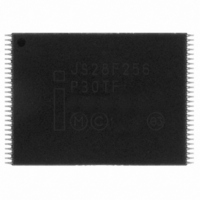
JS28F256P30TFA NUMONYX, JS28F256P30TFA Datasheet - Page 48

JS28F256P30TFA
Manufacturer Part Number
JS28F256P30TFA
Description
IC FLASH 256MBIT 110NS 56TSOP
Manufacturer
NUMONYX
Series
Axcell™r
Datasheet
1.PF48F4000P0ZBQEF.pdf
(94 pages)
Specifications of JS28F256P30TFA
Format - Memory
FLASH
Memory Type
FLASH
Memory Size
256M (16Mx16)
Speed
110ns
Interface
Parallel
Voltage - Supply
1.7 V ~ 2 V
Operating Temperature
-40°C ~ 85°C
Package / Case
56-TSOP
Package
56TSOP
Cell Type
NOR
Density
256 Mb
Architecture
Sectored
Block Organization
Asymmetrical
Location Of Boot Block
Top
Typical Operating Supply Voltage
1.8 V
Sector Size
32KByte x 4|128KByte x 255
Timing Type
Asynchronous|Synchronous
Interface Type
Parallel|Serial
Lead Free Status / RoHS Status
Lead free / RoHS Compliant
Other names
902052
902052
JS28F256P30TF 902052
902052
JS28F256P30TF 902052
Available stocks
Company
Part Number
Manufacturer
Quantity
Price
Company:
Part Number:
JS28F256P30TFA
Manufacturer:
MICRON
Quantity:
946
Part Number:
JS28F256P30TFA
Manufacturer:
MICRON/镁光
Quantity:
20 000
12.0
12.1
12.2
Table 20: Power and Reset
Datasheet
48
Notes:
1.
2.
3.
4.
5.
6.
7.
Num
P1
P2
P3
t
t
t
These specifications are valid for all device versions (packages and speeds).
The device may reset if t
Not applicable if RST# is tied to Vcc.
Sampled, but not 100% tested.
When RST# is tied to the V
When RST# is tied to the V
Reset completes within t
Symbol
PLPH
PLRH
VCCPH
Power and Reset Specifications
Power-Up and Power-Down
Power supply sequencing is not required if VPP is connected to VCC or VCCQ. Otherwise
V
Power supply transitions should only occur when RST# is low. This protects the device
from accidental programming or erasure during power transitions.
Reset Specifications
Asserting RST# during a system reset is important with automated program/erase
devices because systems typically expect to read from flash memory when coming out
of reset. If a CPU reset occurs without a flash memory reset, proper CPU initialization
may not occur. This is because the flash memory may be providing status information,
instead of array data as expected. Connect RST# to the same active low reset signal
used for CPU initialization.
Also, because the device is disabled when RST# is asserted, it ignores its control inputs
during power-up/down. Invalid bus conditions are masked, providing a level of memory
protection.
CC
RST# pulse width low
RST# low to device reset during erase
RST# low to device reset during program
V
CC
and V
Power valid to RST# de-assertion (high)
CCQ
PLPH
PLPH
should attain their minimum operating voltage before applying V
CC
CCQ
if RST# is asserted while no erase or program operation is executing.
is < t
supply, device will not be ready until t
supply, device will not be ready until t
Parameter
PLPH MIN
, but this is not guaranteed.
VCCPH
VCCPH
Min
100
300
-
-
after V
after V
CC
CC
Max
≥ V
25
25
≥ V
-
-
CCMIN
CCMIN
.
.
Order Number: 320002-10
Unit
ns
us
P30-65nm
PP
1,2,3,4
1,3,4,7
1,3,4,7
1,4,5,6
Notes
Mar 2010
.


