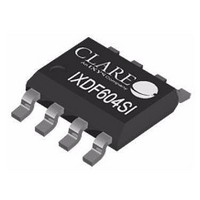
IXDF604SITR Clare, IXDF604SITR Datasheet - Page 11

IXDF604SITR
Manufacturer Part Number
IXDF604SITR
Description
IC GATE DVR 4A DUAL HS 8SOIC
Manufacturer
Clare
Type
Dual Low-Side Ultrafast MOSFET Driversr
Datasheet
1.IXDN604SIA.pdf
(13 pages)
Specifications of IXDF604SITR
Configuration
Low-Side
Input Type
Inverting and Non-Inverting
Delay Time
29ns
Current - Peak
4A
Number Of Configurations
2
Number Of Outputs
2
Voltage - Supply
4.5 V ~ 35 V
Operating Temperature
-40°C ~ 125°C
Mounting Type
Surface Mount
Package / Case
8-SOIC (0.154", 3.90mm Width) Exposed Pad
Product
MOSFET Gate Drivers
Rise Time
9 ns
Fall Time
8 ns
Propagation Delay Time
29 ns
Supply Voltage (max)
35 V
Supply Voltage (min)
4.5 V
Supply Current
10 uA
Maximum Operating Temperature
+ 125 C
Mounting Style
SMD/SMT
Minimum Operating Temperature
- 40 C
Number Of Drivers
2
Output Current
4 A
Lead Free Status / RoHS Status
Lead free / RoHS Compliant
High Side Voltage - Max (bootstrap)
-
Lead Free Status / Rohs Status
Lead free / RoHS Compliant
5.4 Mechanical Dimensions
R02
5.4.1 SIA (8-
5.4.2 SI (8-
(0.228 / 0.244)
(0.228 / 0.244)
(0.090 / 0.110)
(0.130 / 0.150)
(0.012 / 0.020)
(0.012 / 0.020)
5.80 / 6.20
5.80 / 6.20
0.31 / 0.51
2.29 / 2.79
3.30 / 3.81
0.31 / 0.51
Pin
Pin
Power SOIC with Exposed Metal Back)
PIN 1
PIN 1
SOIC)
(0.190 / 0.197)
(0.190 / 0.197)
4.80 / 5.00
4.80 / 5.00
(0.05 BSC)
(0.05 BSC)
(0.150 / 0.157)
(0.150 / 0.157)
1.27 BSC
1.27 BSC
3.80 / 4.00
3.80 / 4.00
(0.051 / 0.069)
(0.051 / 0.069)
1.30 / 1.75
1.30 / 1.75
(0.001 / 0.004)
(0.004 / 0.010)
0.03 / 0.10
0.10 / 0.25
(0.010 / 0.020 x45º)
(0.010 / 0.020 x45º)
0.25 / 0.50 x45º
0.25 / 0.50 x45º
(0.004 / 0.010)
www.clare.com
(0.004 / 0.010)
0.10 / 0.25
0.10 / 0.25
0º / 8º
0º / 8º
(inches MIN / inches MAX)
NOTES:
1. Molded package conforms to JEDEC standard configuration
2. The exposed metal pad on the back of the SI package may be
NOTE: Molded package conforms to JEDEC standard configuration
(0.016 / 0.050)
(0.016 / 0.050)
(inches MIN / inches MAX)
MS-012 variation BA.
left floating or connected to GND. It is not suitable for carrying
current.
0.40 / 1.27
0.40 / 1.27
mm MIN / mm MAX
mm MIN / mm MAX
Dimensions
MS-012 variation AA.
Dimensions
Recommended PCB Land Pattern
Recommended PCB Land Pattern
(0.209)
5.40
(0.050)
(0.108)
1.27
(0.213)
2.75
5.40
(0.150)
(0.024)
3.80
0.60
(0.061)
(0.061)
1.55
(0.024)
(0.050)
1.55
0.60
1.27
IXD_604
11


