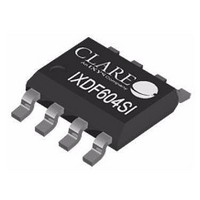
IXDN604SITR Clare, IXDN604SITR Datasheet - Page 13

IXDN604SITR
Manufacturer Part Number
IXDN604SITR
Description
IC GATE DVR 4A DUAL HS 8SOIC
Manufacturer
Clare
Type
Dual Low-Side Ultrafast MOSFET Driversr
Datasheet
1.IXDN604SIA.pdf
(13 pages)
Specifications of IXDN604SITR
Configuration
Low-Side
Input Type
Non-Inverting
Delay Time
29ns
Current - Peak
4A
Number Of Configurations
2
Number Of Outputs
2
Voltage - Supply
4.5 V ~ 35 V
Operating Temperature
-40°C ~ 125°C
Mounting Type
Surface Mount
Package / Case
8-SOIC (0.154", 3.90mm Width) Exposed Pad
Product
MOSFET Gate Drivers
Rise Time
9 ns
Fall Time
8 ns
Propagation Delay Time
29 ns
Supply Voltage (max)
35 V
Supply Voltage (min)
4.5 V
Supply Current
10 uA
Maximum Operating Temperature
+ 125 C
Mounting Style
SMD/SMT
Minimum Operating Temperature
- 40 C
Number Of Drivers
2
Output Current
4 A
Lead Free Status / RoHS Status
Lead free / RoHS Compliant
High Side Voltage - Max (bootstrap)
-
Lead Free Status / Rohs Status
Lead free / RoHS Compliant
Available stocks
Company
Part Number
Manufacturer
Quantity
Price
Company:
Part Number:
IXDN604SITR
Manufacturer:
IXYS
Quantity:
4 300
Part Number:
IXDN604SITR
Manufacturer:
IXYS/艾赛斯
Quantity:
20 000
For additional information please visit our website at: www.clare.com
Clare, Inc. makes no representations or warranties with respect to the accuracy or completeness of the contents of this publication and reserves the right to make changes to specifications and
product descriptions at any time without notice. Neither circuit patent licenses nor indemnity are expressed or implied. Except as set forth in Clare’s Standard Terms and Conditions of Sale,
Clare, Inc. assumes no liability whatsoever, and disclaims any express or implied warranty, relating to its products including, but not limited to, the implied warranty of merchantability, fitness for
a particular purpose, or infringement of any intellectual property right.
The products described in this document are not designed, intended, authorized or warranted for use as components in systems intended for surgical implant into the body, or in other
applications intended to support or sustain life, or where malfunction of Clare’s product may result in direct physical harm, injury, or death to a person or severe property or environmental
damage. Clare, Inc. reserves the right to discontinue or make changes to its products at any time without notice.
R02
Embossed Carrier
5.4.5 D2 (8-
5.4.6 Tape & Reel Information for D2 Package
(0.014 / 0.018 x 45º)
(0.037 BSC)
0.95 BSC
0.35 / 0.45 x 45º
(0.158 BSC)
4.00 BSC
Pin
(13.00 DIA.)
330.2 DIA.
Top Cover
Tape Thickness
0.102 MAX.
(0.004 MAX.)
DFN)
Pin 1
Pin 1
Embossment
(0.030 / 0.032)
(0.197 BSC)
0.76 / 0.81
5.00 BSC
B
0
=5.40 ± 0.10
5º MAX
(0.100 / 0.102)
2.54 / 2.59
K
0
=1.90 ± 0.10
Pin 8
R0.75 TYP
(0.012 / 0.018)
0.30 / 0.45
(0.031 / 0.039)
0.80 / 1.00
(0.000 / 0.002)
0.30 ± 0.05
www.clare.com
(0.120 / 0.122)
0.00 / 0.05
3.04 / 3.09
5º MAX
4.00 ± 0.10 See Note #2
NOTE:
The exposed metal pad on the back of the D2 package may be
left floating or connected to ground. It is not suitable for carrying current.
(0.008 REF)
2.00 ± 0.05
0.20 REF
A
0
=4.25 ± 0.10
(0.018)
0.45
(0.037)
Recommended PCB Land Pattern
0.95
(0.047)
1.20
8.00 ± 0.10
(0.014 x 45º)
NOTES:
1. A
2. 10 pitches cumulative tol. ± 0.2mm
3. ( ) Reference dimensions only.
4. Unless otherwise specified, all dimensions in millimeters.
0.35 x 45º
(0.05)
0
& B
Specification: DS-IXD_604-R02
©Copyright 2010, Clare, Inc.
All rights reserved. Printed in USA.
12/3/2010
∅1.55 ± 0.05
0
measured at 0.3mm above base of pocket.
(0.05)
(0.177)
(0.100)
(inches MIN / inches MAX)
4.50
2.55
mm MIN / mm MAX
Dimensions
1.75 ± 0.10
∅1.50 (MIN)
(0.120)
5.50 ± 0.05
3.05
IXD_604
12.00 ± 0.30
13


