91A1A-B24-B20L Bourns Inc., 91A1A-B24-B20L Datasheet - Page 3
91A1A-B24-B20L
Manufacturer Part Number
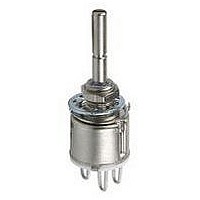
91A1A-B24-B20L
Description
POT 100K OHM 5/8" SQ 1/2W PLAS
Manufacturer
Bourns Inc.
Series
91r
Type
Potentiometerr
Datasheets
1.91A1A-B28-B15L.pdf
(5 pages)
2.91A1A-B24-B10L.pdf
(6 pages)
3.91A1A-B28-B10L.pdf
(5 pages)
Specifications of 91A1A-B24-B20L
Adjustment Type
Side Adjustment
Resistance (ohms)
100K
Power (watts)
0.5W, 1/2W
Tolerance
±20%
Temperature Coefficient
±1000ppm/°C
Number Of Turns
Single
Rotation
300°
Resistive Material
Conductive Plastic
Termination Style
Through Hole
Actuator Length
19.05mm
Actuator Type
Slotted Shaft
Actuator Diameter
6.35mm
Package / Case
Square - 0.625" L x 0.500" W x 0.687" H (15.88mm x 12.70mm x 17.45mm)
Track Resistance
100kohm
Track Taper
Linear
No. Of Turns
1
Resistance Tolerance
± 20%
Power Rating
500mW
Potentiometer Mounting
Panel
No. Of Gangs
1
Resistance
100 KOhms
Taper
Linear
Element Type
Conductive Plastic
Shaft Type
Slotted
Shaft Length
3/4 in
Shaft Diameter
1/4 in
Angle, Mechanical
300 °
Diameter, Shaft
0.25 "
Dielectric Strength
1500 VAC
Dimensions
0.625"L×0.625"W×0.5"H
Linearity
±5 %
Material, Element
Conductive Plastic
Mounting Type
Panel
Power, Rating
0.5 W
Resistance, Insulation
1000 Megohms
Resolution
Infinite
Rotational Life
100000 Cycles
Temperature, Operating, Maximum
+125 °C
Temperature, Operating, Minimum
-40 °C
Termination
PC Pins
Torque
0.3 N-cm
Lead Free Status / RoHS Status
Lead free / RoHS Compliant
Lead Free Status / RoHS Status
Lead free / RoHS Compliant, Lead free / RoHS Compliant
Available stocks
Company
Part Number
Manufacturer
Quantity
Price
Company:

Part Number:
91A1A-B24-B20L
Manufacturer:
BOURNS
Quantity:
1 000


Contacts:
Power Rating (Resistive Load):
Contact Resistance (0.1 VDC-10 mA)........................................................................................................................................................10 milliohms nominal
Contact Bounce ..................................................................................................................................................................................5 milliseconds maximum
Dielectric Withstanding Voltage (MIL-STD-202, Method 301)
Insulation Resistance ..........................................................................................................................................................................1000 megohms minimum
Operating Temperature Range ............................................................................................................................................................................0 °C to +70 °C
Exposure Temperature Range ........................................................................................................................................................................-65 °C to +125 °C
Vibration (Dual Section)..........................................................................................................................................................................................................8 G
Shock (Dual Section)............................................................................................................................................................................................................20 G
Rotational Life........................................................................................................................................................................................................25,000 cycles
Moisture Resistance (MIL-STD-202, Method 106, Condition B)
Housing Material................................................................................................................................High temperature, flame retardant, thermosetting plastic
Actuating Torque (Each Section, Switch Module Only) ......................................................................................................3.53 to 10.59 N-cm (5 to 15 oz.-in.)
Running Torque (Out of Detent, 2-4 Module Assembly) ......................................................................................................0.21 to 1.41 N-cm (0.3 to 2 oz.-in.)
Detent ......................................................................................................................................................................................................CW or CCW standard
Actuation Angle..............................................................................................................................................................................................................20 ° ±5 °
Contact Materials ............................................................................................................................................................................Fine silver with gold overlay
Terminal Styles ....................................................................................................................................................................................................Solder lug only
Terminal Strength (Before and After Soldering Heat Exposure) ............................................................................................................0.9 kg (2 lbs.) minimum
NOTE: Model 99 performance specifications do not apply to units subjected to printed circuit board cleaning procedures.
1
At room ambient: +25 °C nominal and 50 % relative humidity nominal, except as noted.
Rotary Switch Specifications
Initial Electrical Characteristics
Environmental Characteristics
Mechanical Characteristics
DPST ..................................................................................................................................................................................N.O/N.O., N.C./N.C. or N.O./N.C.
DPDT....................................................................................................................................................................................2 N.O./N.C. (break before make)
DPST ................................................................................................................2 A @ 125 volts RMS-60 Hz or 2 A @ 28 VDC, 1 A @ 250 volts RMS-60 Hz
DPDT ..............................................................................................................................................................1 A @ 125 volts RMS-60 Hz or 1 A @ 28 VDC
Sea Level ................................................................................................................................................................................................1500 VAC minimum
Contact Resistance ............................................................................................................................................................................10 milliohms maximum
Contact Bounce..............................................................................................................................................................................0.1 millisecond maximum
Switch Actuating Torque (50% Duty cycle @ Rated Power Load) ......................................................................................1.41 to 4.94 N-cm (2 to 7 oz.-in.)
Contact Resistance ..........................................................................................................................................................................100 milliohms maximum
Contact Resistance (0.1 VDC-10 mA) ................................................................................................................................................10 milliohms maximum
Insulation Resistance (After 24 Hours @ Room Temperature) (500 VDC) ........................................................................................100 megohms minimum
Standard Orientation ..................................................................................................................................................................In-line with control terminals
Optional..............................................................................................................................................................................Rotated 90 ° CCW from standard
Specifications are subject to change without notice.
Customers should verify actual device performance in their specific applications.
91, 92, 93, 94, 95, 96 - 5/8 ” Square Single-Turn Panel Control
97, 99 - 5/8 ” Square Single-Turn Panel Control with Rotary Switch
1
1
1
Related parts for 91A1A-B24-B20L
Image
Part Number
Description
Manufacturer
Datasheet
Request
R

Part Number:
Description:
POT 10K OHM COND PLAST 1/2W
Manufacturer:
Bourns Inc.
Datasheet:
Part Number:
Description:
POT 5K OHM COND PLAST 1/2W
Manufacturer:
Bourns Inc.
Datasheet:
Part Number:
Description:
POT 5K OHM COND PLAST 1/2W
Manufacturer:
Bourns Inc.
Datasheet:
Part Number:
Description:
POT 10K OHM COND PLAST 1/2W
Manufacturer:
Bourns Inc.
Datasheet:
Part Number:
Description:
POT 50K OHM 5/8" 1/2W PLAST
Manufacturer:
Bourns Inc.
Datasheet:
Part Number:
Description:
POT 100K OHM 5/8" 1/2W PLAST
Manufacturer:
Bourns Inc.
Datasheet:
Part Number:
Description:
POT 10K OHM COND PLAS AUDIO 1/4W
Manufacturer:
Bourns Inc.
Datasheet:
Part Number:
Description:
POT 10K OHM COND PLAS AUDIO 1/4W
Manufacturer:
Bourns Inc.
Datasheet:
Part Number:
Description:
POT 100K OHM 5/8" 1/4W PLAST
Manufacturer:
Bourns Inc.
Datasheet:

Part Number:
Description:
POT 25K OHM 5/8" SQ 1/2W PLAS
Manufacturer:
Bourns Inc.
Datasheet:

Part Number:
Description:
Manufacturer:
Bourns, Inc.
Datasheet:
Part Number:
Description:
11mm Potentiometer
Manufacturer:
Bourns, Inc.
Datasheet: