3400S-1-102L Bourns Inc., 3400S-1-102L Datasheet
3400S-1-102L
Manufacturer Part Number
3400S-1-102L
Description
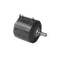
POT 1.0K OHM 1-13/16" RD WW
Manufacturer
Bourns Inc.
Series
3400r
Type
Potentiometerr
Datasheet
1.3400S-1-102L.pdf
(1 pages)
Specifications of 3400S-1-102L
Tolerance
±3%
Termination Style
Solder Lug
Number Of Turns
10
Resistance (ohms)
1K
Power (watts)
5W
Temperature Coefficient
±20ppm/°C
Rotation
1800°
Adjustment Type
Side Adjustment
Resistive Material
Wirewound
Actuator Length
20.64mm
Actuator Type
Slotted Shaft
Actuator Diameter
6.34mm
Package / Case
Round - 1.813" Dia x 1.750" H (46.04mm x 44.45mm)
Resistance
1 KOhms
Power Rating
5 Watts
Element Type
Wire Wound
Shaft Type
Slotted
Shaft Length
20.64 mm
Shaft Diameter
6.34 mm
Product
Precision Potentiometers
Angle, Mechanical
3600 °
Diameter, Shaft
0.2497 "
Dielectric Strength
1000 VAC
Dimensions
1-13/16"Dia×1-3/4"L
Linearity
±0.15 %
Material, Element
Wirewound
Mounting Type
Panel
Power, Rating
5 W
Resistance, Insulation
1000 Megohms
Resolution
0.02 %
Rotational Life
2000000 Revolutions
Taper
Linear
Temperature, Operating, Maximum
+125 °C
Temperature, Operating, Minimum
+1 °C
Termination
Lug
Torque
1.4 N-cm
Operating Temperature Range
+1°C to +125°C
Resistance Tolerance
±3%
Independent Linearity
±0.15%
Rotational Life (no Load)
2,000,000 Shaft Revolutions
End Voltage
15% Max.Features
Mounting Style
Panel
Track Resistance
1kohm
Track Taper
Linear
No. Of Turns
10
Potentiometer Mounting
Panel
No. Of Gangs
2
Leaded Process Compatible
Yes
Rohs Compliant
Yes
Lead Free Status / RoHS Status
Lead free / RoHS Compliant
Lead Free Status / RoHS Status
Lead free / RoHS Compliant, Lead free / RoHS Compliant
Available stocks
Company
Part Number
Manufacturer
Quantity
Price
Company:

Part Number:
3400S-1-102L
Manufacturer:
COPAL
Quantity:
20 000
Standard Resistance Range .........................................................................100 to 500 K ohms
Total Resistance Tolerance .................................................................................................±3 %
Independent Linearity ....................................................................................................±0.15 %
Effective Electrical Angle ...................................................................................3600 ° +4 °, -0 °
Absolute Minimum Resistance .................... 1 ohm or 0.15 % maximum (whichever is greater)
Noise ................................................................................................ 100 ohms ENR maximum
Dielectric Withstanding Voltage....................................................... MIL-STD-202, Method 301
Power Rating (Voltage Limited By Power Dissipation, or ....................................(40 °C) 5 watts
Insulation Resistance (500 VDC) .......................................................1,000 megohms minimum
Resolution ............................................................................... See recommended part number
Operating Temperature Range ........................................................................+1 °C to +125 °C
Storage Temperature Range ..........................................................................-65 °C to +125 °C
Temperature Coeffi cient Over Storage Temperature Range
Vibration ..............................................................................................................................10 G
Shock ..................................................................................................................................50 G
Load Life .....................................................................................................1,000 hours, 5 watts
Rotational Life (No Load) .............................................................. 2,000,000 shaft revolutions
Moisture Resistance (MIL-STD-202, Method 103, Condition B)
IP Rating ............................................................................................................................. IP 40
Stop Strength ......................................................................................53 N-cm (75 oz.-in.) min.
Mechanical Angle ........................................1080 ° +10 °, -0 ° (3543); 1800 ° +10 °, -0 ° (3545)
Torque (Starting & Running) ............................................................0.35 N-cm (0.5 oz.-in.) max.
Shaft Runout .......................................................................................0.08 mm (0.003 in.) T.I.R.
Lateral Runout .....................................................................................0.13 mm (0.005 in.) T.I.R.
Shaft End Play .....................................................................................0.25 mm (0.010 in.) T.I.R.
Shaft Radial Play .................................................................................0.08 mm (0.003 in.) T.I.R.
Pilot Diameter Runout .........................................................................0.08 mm (0.003 in.) T.I.R.
Backlash ............................................................................................................. 1.0 ° maximum
Weight ...................................................................................................... Approximately 21 gm
Terminals ...............................................................................................Gold-plated solder lugs
Soldering Condition
Marking ....................................... Manufacturer’s name and part number, resistance value and
Ganging (Multiple Section Pots.) .....................................................................2 cups maximum
Hardware ..........................................One lockwasher (H-37-2) and one mounting nut (H-38-2)
1 At room ambient: +25 °C nominal and 50 % relative humidity nominal, except as noted.
2 Consult manufacturer for complete specifi cation details for resistances below 500 ohms and above
Part Number
3400S-1-102L
3400S-1-502L
3400S-1-103L
Electrical Characteristics
Sea Level ................................................................................................1,000 VAC minimum
80,000 Feet ................................................................................................300 VAC minimum
1,000 VAC, Whichever Is Less) ........................................................................(125 °C) 0 watt
Environmental Characteristics
Wiper Bounce ................................................................................ 0.1 millisecond maximum
Total Resistance Shift ....................................................................................±2 % maximum
Voltage Ratio Shift ......................................................................................±0.1 % maximum
Total Resistance Shift ....................................................................................±2 % maximum
Total Resistance Shift ....................................................................................±5 % maximum
Total Resistance Shift ....................................................................................±2 % maximum
Mechanical Characteristics
Mounting ....................................................................................170-200 N-cm (15-18 lb.-in.)
Wave Soldering ........... 96.5Sn/3.0Ag/0.5Cu solder with no-clean fl ux; 260 °C (500 °F) max.
Wash processes ....................................................................................... Not recommended
Manual Soldering ............................................... 96.5Sn/3.0Ag/0.5Cu solid wire or no-clean
Recommended Part Numbers
100K ohms.
Resistance (Ω)
10,000
1,000
5,000
1
Resolution (%)
tolerance, linearity tolerance, wiring diagram, and date code.
1
.020
.013
.010
1
rosin cored wire; 370 °C (700 °F) max. for 3 seconds
BOLDFACE LISTINGS ARE IN STOCK AND READILY AVAILABLE
THROUGH DISTRIBUTION.
FOR OTHER OPTIONS CONSULT FACTORY.
ROHS IDENTIFIER:
L = COMPLIANT
Features
■
■
■
■
■
3400 - Precision Potentiometer
Bushing mount
Optional ±0.05 linearity option
Excellent wiper stability
High stop strength
Sealable
is shipped with each potentiometer.
2
.........±20 ppm/°C maximum/unit
BLANK = NON-COMPLIANT
for 5 seconds
Customers should verify actual device performance in their specifi c applications.
2
*RoHS Directive 2002/95/EC Jan 27, 2003 including Annex
(1-5/32)
X
RECOMMENDED PANEL LAYOUT
29.37
WIPER
(.04)
(.04)
Product Dimensions
1.02
1.02
1-13/16
(46.04)
DIA.
Specifi cations are subject to change without notice.
CCW
Model 3400 is currently available,
WIDE
SLOT
DEEP
although not recommended for new
RECOMMENDED PCB THICKNESS:
MOUNTING TORQUE: 15-18 LB.-IN.
TOLERANCES: EXCEPT WHERE NOTED
DECIMALS: .XX ±
FRACTIONS: ±1/64
DIMENSIONS:
designs.
1
CCW
(3/16)
(1-3/4 ± 1/32)
TYP.
4.76
44.45 ± .79
EXTENDS
(.132 +.003/-.001)
(.125)
CLOCKWISE
3.18
3.35 +.08/-.03
(13/16)
20.64
1.52
(.06)
Model 3500
7.94
5/16
( IN.)
DIA. ANTI-ROTATION PIN
MM
CW
(.410 ± .003)
(.010),
10.41 ± .08
1.02
(.04)
.25
2
(.563 ± .002)
14.30 ± .05
(.093)
2.36
WIPER
(1/4)
6.35
PAST MOUNTING SURFACE
.XXX ±
DIA.
DIA. TYP.
(.2497 + .0000/ - .0003)
3/8 "-32 2A THD UNEF
(9/16)
is preferred.
DIA.
REV. 09/28/10
14.3
(.005)
.13
(.4062 + .000/ -.002)
6.34 + .00/ - .01
R
ADD
ADDITIONAL CUP
10.32 + .00/ - .05
SHAFT DIA.
(.097)
3
2.46
45 ° X .25
CHAMFER
PILOT DIA.
(1.55)
CW
39.4
FOR
Related parts for 3400S-1-102L
Image
Part Number
Description
Manufacturer
Datasheet
Request
R

Part Number:
Description:
POT 10K OHM 1-13/16" RD WW
Manufacturer:
Bourns Inc.
Datasheet:

Part Number:
Description:
POT 5.0K OHM 1-13/16" RD WW
Manufacturer:
Bourns Inc.
Datasheet:
Part Number:
Description:
Precision Potentiometers 1-13/16 20KOHMS 0.15% WW 10TURNS
Manufacturer:
Bourns Inc.
Datasheet:
Part Number:
Description:
Precision Potentiometers 1-13/16 10KOHMS 0.15% WW 10TURNS
Manufacturer:
Bourns Inc.
Datasheet:
Part Number:
Description:
Precision Potentiometers 1-13/16 2KOHMS 0.15% WW 10TURNS
Manufacturer:
Bourns Inc.
Datasheet:
Part Number:
Description:
POT 100 OHM 1-13/16" RD WW
Manufacturer:
Bourns Inc.
Datasheet:
Part Number:
Description:
POT 200 OHM 1-13/16" RD WW
Manufacturer:
Bourns Inc.
Datasheet:
Part Number:
Description:
POT 2.0K OHM 1-13/16" RD WW
Manufacturer:
Bourns Inc.
Datasheet:
Part Number:
Description:
POT 500 OHM 1-13/16" RD WW
Manufacturer:
Bourns Inc.
Datasheet:
Part Number:
Description:
POT 20K OHM 1-13/16" RD WW
Manufacturer:
Bourns Inc.
Datasheet:

Part Number:
Description:
Manufacturer:
Bourns, Inc.
Datasheet:
Part Number:
Description:
11mm Potentiometer
Manufacturer:
Bourns, Inc.
Datasheet: