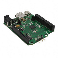
VNCLO-MB1A FTDI, Future Technology Devices International Ltd, VNCLO-MB1A Datasheet

VNCLO-MB1A
Specifications of VNCLO-MB1A
768-1088-
Related parts for VNCLO-MB1A
VNCLO-MB1A Summary of contents
Page 1
Future Technology Devices International Ltd. Vinco LCD Interface Example Application Note AN_153 This application note describes how the Vinco module can be used to provide an interface to a Future Technology Devices International Ltd (FTDI) Unit 1, 2 Seaward Place, ...
Page 2
Introduction Vinco is a development module inspired by the Arduino concept and uses the Vinculum II, VNC2 device. Vinco uses a VNC2-64Q package to facilitate 38 GPIO options on 0.1” pitch sockets. Vinco is designed as a prototyping ...
Page 3
Topway LCD Display This application example uses the Topway LMB162ABC 16 character 2 line LCD display. The display is driven power supply and 4 data lines control the characters displayed on the display. For more ...
Page 4
Table of Contents 1 Introduction .................................................................... 1 1.1 VNC2 Devices ............................................................................ 1 1.2 Topway LCD Display .................................................................. 2 2 Block Diagram ................................................................. 4 3 Interconnect ................................................................... 5 3.1 Power ....................................................................................... 5 3.2 LCD Control ............................................................................... 5 3.3 Debugger Interface ...
Page 5
Block Diagram This block diagram, Figure 2.1, shows the interconnect required for the Vinco to drive the LCD display. The Vinco debug port is used to load the firmware onto the module. (Note that this requires a VNC2 ...
Page 6
... Table 3.1 - Signal Name and Description – LCD Interface Copyright © 2010 Future Technology Devices International Limited Document Reference No.: FT_000332 AN_153 Vinco LCD Interface Example VNCLO-PSU-UK) Function Data lines for sending information to the LCD Register Select is used to determine if the information being sent to the LCD panel is display data (RS= instruction ( ...
Page 7
Debugger Interface The purpose of the debugger interface is to provide access to the VNC2 silicon/firmware debugger. The debug interface can be accessed by connecting a VNC2_Debug_Module (http://www.ftdichip.com/Support/Documents/DataSheets/ICs/DS_Vinculum-II.pdf This debug module gives access to the debugger through a ...
Page 8
Source code for the VNC2 writing to LCD Display The Vinculum II IDE is used to create application code to run on VNC2. This section gives some example source code, and explains its operation, used to drive the ...
Page 9
Note: Starting the VOS scheduler is always the last thing to be done as all configuration must be complete before this starts. 4.2 LCD Initialisation The LCD must be put into an initial known state to be able ...
Page 10
VOS defined command for writing out data. The hLCD is the handle for the driver that the data is being sent to. In this example that means the GPIO lines. ...
Page 11
The Firmware function The “firmware” function in this example defines the variables used, the text to be sent to the display and calling the LCD control functions. void firmware(void VOS handles for opened devices VOS_HANDLE hGpio; ...
Page 12
Programming Vinco When Vinco has been connected to the LCD panel and the firmware has been built in the IDE, the next step is to transfer the .ROM file generated by the IDE to the Vinco module. The ...
Page 13
Running the firmware The Vinco may be reset by power cycling the unit and then the firmware will run... The user will observe text on the LCD being updated as per the firmware code: Vinco www.ftdichip.com The best ...
Page 14
Contact Information Head Office – Glasgow, UK Future Technology Devices International Limited Unit 1, 2 Seaward Place, Centurion Business Park Glasgow, G41 1HH United Kingdom Tel: +44 (0) 141 429 2777 Fax: +44 (0) 141 429 2758 E-mail ...
Page 15
Appendix A – References Application and Technical Notes available at http://www.ftdichip.com/Support/Documents/AppNotes.htm Vinco datasheet http://www.ftdichip.com/Support/Documents/DataSheets/ICs/DS_Vinculum-II.pdf VNC2 Debug Module http://www.ftdichip.com/Support/Documents/DataSheets/ICs/DS_Vinculum-II.pdf Vinculum-II IO Cell Description http://www.ftdichip.com/Support/Documents/AppNotes/AN_137_Vinculum- II%20IO_Cell_Description.pdf Vinculum-II Debug Interface Description http://www.ftdichip.com/Support/Documents/AppNotes/AN_138_Vinculum- II_Debug_Interface_Description.pdf Vinculum-II IO Mux Explained http://www.ftdichip.com/Support/Documents/AppNotes/AN_139_Vinculum- II%20IO_Mux%20Explained.pdf Vinculum-II Errata Technical ...
Page 16
Appendix B – List of Figures and Tables List of Figures Figure 1.1 - VINCO ....................................................................................................................... 1 Figure 2.1 – Vinco Sign Writer Demo Block Diagram ......................................................................... 4 List of Tables Table 3.1 - Signal Name and Description – ...
Page 17
Appendix C – Revision History Version draft First draft Version 1.0 First Release Version 2.0 Change brand name from Vinculo to Vinco Copyright © 2010 Future Technology Devices International Limited Document Reference No.: FT_000332 AN_153 Vinco LCD Interface Example ...


