Y16362K50000T9W Vishay, Y16362K50000T9W Datasheet - Page 2
Y16362K50000T9W
Manufacturer Part Number
Y16362K50000T9W
Description
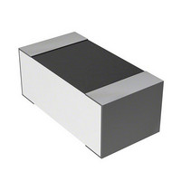
RES 2.5K OHM .1W .01% FOIL 0603
Manufacturer
Vishay
Series
VSMPr
Datasheet
1.Y16362K00000T9W.pdf
(5 pages)
Specifications of Y16362K50000T9W
Featured Product
Bulk Metal® Z-Foil Wraparound Surface-Mount Resistor
Resistance (ohms)
2.5K
Number Of Terminations
2
Package / Case
0603 (1608 Metric)
Power (watts)
0.1W, 1/10W
Composition
Metal Foil
Features
Non-Inductive
Temperature Coefficient
±0.2ppm/°C
Tolerance
±0.01%
Size / Dimension
0.063" L x 0.032" W (1.60mm x 0.81mm)
Height
0.025" (0.64mm)
Lead Free Status / RoHS Status
Lead free / RoHS Compliant
Other names
804-1017
804-1017
VSMP0603 2K5 0.01% S W
Y1636-2.5K
804-1017
VSMP0603 2K5 0.01% S W
Y1636-2.5K


VSMP0603 (Z-Foil)
Vishay Foil Resistors
Note
• Land pattern dimensions are per IPC-782.
Note
• As shown + 0.01 to allow for measurement errors at low values.
www.foilresistors.com
2
Interloop Capacitance
Reduction in Series
FIGURE 2 - TRIMMING TO VALUES
TABLE 2 - DIMENSIONS AND LAND PATTERN in Inches (Millimeters)
CHIP SIZE
0603
TABLE 3 - PERFORMANCES
Thermal shock:
100 x (- 65 °C to + 150 °C)
Low temperature operation:
- 65 °C, 45 min, rated power
Short time overload:
6.25 x rated power, 5 s
High temperature exposure: 100 h, 150 °C
Resistance to soldering heat
Moisture resistance
Load life stability + 70 °C for 2000 h
at rated power
Mutual Inductance
Reduction due
to Opposing
Current in
Adjacent Lines
TEST OR CONDITIONS
PER MIL-PRF-55342
(Conceptual Illustration)
Note: Foil shown in black, etched spaces in white
± 0.005 (0.13)
0.063 (1.60)
L
After Trimming
Current Path
T
from Shorting Strip Area
CHARACTERISTIC E R LIMITS
Changing Current Path
Removes this Material
For any questions, contact:
Uncoated
Ceramic
Trimming Process
and Increasing
Resistance
Before Trimming
Current Path
MIL-PRF-55342
Bottom View for Mounting
± 0.005 (0.13)
0.032 (0.81)
± 0.2 %
± 0.1 %
± 0.1 %
± 0.1 %
± 0.2 %
± 0.5 %
± 0.2 %
D
W
Note
• The TCR values for < 100 are influenced by the termination
foil@vishaypg.com
FIGURE 3 -TYPICAL TCR CURVE Z-FOIL
composition and result in deviation from this curve.
L
(ppm)
ΔR
R
+ 500
+ 400
+ 300
+ 200
+ 100
- 100
- 200
- 300
- 400
- 500
THICKNESS MAXIMUM
0
TYPICAL R LIMITS
± 0.005 % (50 ppm)
± 0.005 % (50 ppm)
± 0.005 % (50 ppm)
± 0.01 % (100 ppm)
± 0.005 % (50 ppm)
± 0.03 % (300 ppm)
± 0.005 % (50 ppm)
W
- 55
0.025 (0.64)
- 0.16 ppm/°C
- 25
- 0.1 ppm/°C
Ambient Temperature (°C)
0
0.05 ppm/°C
+ 25
0.1 ppm/°C
Document Number: 63141
0.14 ppm/°C
MAXIMUM R LIMITS
+ 60 + 75
± 0.01 % (100 ppm)
± 0.01 % (100 ppm)
± 0.01 % (100 ppm)
± 0.03 % (300 ppm)
± 0.02 % (200 ppm)
± 0.1 % (1000 ppm)
± 0.01 % (100 ppm)
0.2 ppm/°C
± 0.005 (0.13)
Revision: 26-Mar-10
0.011 (0.28)
+ 100 + 125
D
Related parts for Y16362K50000T9W
Image
Part Number
Description
Manufacturer
Datasheet
Request
R

Part Number:
Description:
357-036-542-201 CARDEDGE 36POS DL .156 BLK LOPRO
Manufacturer:
Vishay
Datasheet:
Part Number:
Description:
357-036-542-201 CARDEDGE 36POS DL .156 BLK LOPRO
Manufacturer:
Vishay
Datasheet:
Part Number:
Description:
357-036-542-201 CARDEDGE 36POS DL .156 BLK LOPRO
Manufacturer:
Vishay
Datasheet:
Part Number:
Description:
357-036-542-201 CARDEDGE 36POS DL .156 BLK LOPRO
Manufacturer:
Vishay
Datasheet:
Part Number:
Description:
357-036-542-201 CARDEDGE 36POS DL .156 BLK LOPRO
Manufacturer:
Vishay
Datasheet:
Part Number:
Description:
357-036-542-201 CARDEDGE 36POS DL .156 BLK LOPRO
Manufacturer:
Vishay
Datasheet:
Part Number:
Description:
357-036-542-201 CARDEDGE 36POS DL .156 BLK LOPRO
Manufacturer:
Vishay
Datasheet:
Part Number:
Description:
357-036-542-201 CARDEDGE 36POS DL .156 BLK LOPRO
Manufacturer:
Vishay
Datasheet:
Part Number:
Description:
357-036-542-201 CARDEDGE 36POS DL .156 BLK LOPRO
Manufacturer:
Vishay
Datasheet:
Part Number:
Description:
357-036-542-201 CARDEDGE 36POS DL .156 BLK LOPRO
Manufacturer:
Vishay
Datasheet:
Part Number:
Description:
357-036-542-201 CARDEDGE 36POS DL .156 BLK LOPRO
Manufacturer:
Vishay
Datasheet:
Part Number:
Description:
357-036-542-201 CARDEDGE 36POS DL .156 BLK LOPRO
Manufacturer:
Vishay
Datasheet:
Part Number:
Description:
357-036-542-201 CARDEDGE 36POS DL .156 BLK LOPRO
Manufacturer:
Vishay
Datasheet:
Part Number:
Description:
357-036-542-201 CARDEDGE 36POS DL .156 BLK LOPRO
Manufacturer:
Vishay
Datasheet:
Part Number:
Description:
357-036-542-201 CARDEDGE 36POS DL .156 BLK LOPRO
Manufacturer:
Vishay
Datasheet: