Y1625100R000Q9R Vishay, Y1625100R000Q9R Datasheet - Page 2
Y1625100R000Q9R
Manufacturer Part Number
Y1625100R000Q9R
Description
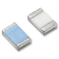
RES 100 OHM .3W .02% FOIL 1206
Manufacturer
Vishay
Series
VSMPr
Datasheet
1.Y16251K00000T9R.pdf
(4 pages)
Specifications of Y1625100R000Q9R
Temperature Coefficient
±0.2ppm/°C
Resistance (ohms)
100
Number Of Terminations
2
Package / Case
1206 (3216 Metric)
Power (watts)
0.3W
Composition
Metal Foil
Features
Non-Inductive
Tolerance
±0.02%
Size / Dimension
0.126" L x 0.062" W (3.20mm x 1.57mm)
Height
0.025" (0.64mm)
Resistance
100ohm
Resistance Tolerance
± 0.02%
Power Rating
300mW
Voltage Rating
5.47V
Resistor Element Material
Metal Film
Resistor Case
RoHS Compliant
Lead Free Status / RoHS Status
Lead free / RoHS Compliant
Other names
VSMP1206 100R000 TCR0.2 0.02% S T
Y1625-100ATR
Y1625-100ATR


VSMP Series (0805, 1206, 1506, 2010, 2512) (Z-Foil)
Vishay Foil Resistors
Note
(1)
Note
(1)
www.foilresistors.com
2
Interloop Capacitance
Reduction in Series
FIGURE 2 - TRIMMING TO VALUES
TABLE 2 - DIMENSIONS AND LAND PATTERN in Inches (Millimeters)
TABLE 3 - SPECIFICATIONS
CHIP
SIZE
0805
1206
1506
2010
2512
TABLE 5 - PERFORMANCES
TEST OR CONDITIONS
Thermal Shock, 100 x (- 65 °C to + 150 °C)
Low Temperature Operation, - 65 °C, 45 min at P
Short Time Overload, 6.25 x Rated Power, 5 s
High Temperature Exposure, + 150 °C, 100 h
Resistance to Soldering Heat
Moisture Resistance
Load Life Stability + 70 °C for 2000 h at Rated Power
Land Pattern Dimensions are per IPC-7351A
As shown + 0.01 Ω to allow for measurement errors at low values.
Mutual Inductance
Reduction due
to Change in
Current Direction
CHIP
SIZE
0805
1206
1506
2010
2512
at + 70 °C
POWER
RATED
(mW)
200
300
300
500
750
(Conceptual Illustration)
± 0.005 (0.13)
Note: Foil shown in black, etched spaces in white
0.080 (2.03)
0.126 (3.20)
0.150 (3.81)
0.198 (5.03)
0.249 (6.32)
T
WORKING
(≤
VOLTAGE
L
MAX.
187 V
220 V
40 V
87 V
95 V
P R
×
)
Top View
± 0.005 (0.13)
RESISTANCE
0.050 (1.27)
0.062 (1.57)
0.062 (1.57)
0.097 (2.46)
0.127 (3.23)
10 to 125K
10 to 25K
10 to 30K
10 to 70K
RANGE
10 to 8K
D
After Trimming
W
(Ω)
Current Path
from Shorting Strip Area
L
Changing Current Path
Removes this Material
For any questions, contact:
Trimming Process
and Increasing
nom
Resistance
Before Trimming
Current Path
MAXIMUM
W
THICKNESS
WEIGHT
0.025 (0.64)
0.025 (0.64)
0.025 (0.64)
0.025 (0.64)
0.025 (0.64)
MAXIMUM
(mg)
11
12
27
40
6
CHARACTERISTIC E ΔR LIMITS
MIL-PRF-55342
± 0.005 (0.13)
± 0.1 %
± 0.1 %
± 0.1 %
± 0.1 %
± 0.2 %
± 0.2 %
± 0.5 %
0.015 (0.38)
0.020 (0.51)
0.020 (0.51)
0.025 (0.64)
0.032 (0.81)
Note
• The TCR values for < 100 Ω are influenced by the termination
foil@vishaypg.com
FIGURE 3 - TYPICAL RESISTANCE/
TABLE 4 - LOAD LIFE STABILITY
CHIP SIZE
0805
1206, 1506
2010
2512
composition and result in deviation from this curve.
(ppm)
D
ΔR
R
Recommended Land Pattern
+ 400
+ 300
+ 200
+ 100
- 100
- 200
- 300
- 400
- 500
Z
0
G
- 55
0.122 (3.10)
0.175 (4.45)
0.199 (5.05)
0.247 (6.27)
0.291 (7.39)
Ambient Temperature (°C) and TCR Chord Slopes for
(+ 70 °C for 2000 h)
TEMPERATURE CURVE
Z
- 0.16 ppm/°C
± 0.005 % (50 ppm)
± 0.005 % (50 ppm)
± 0.005 % (50 ppm)
± 0.01 % (100 ppm)
± 0.005 % (50 ppm)
± 0.005 % (50 ppm)
± 0.005 % (50 ppm)
- 25
(1)
- 0.1 ppm/°C
Different Temperature Ranges
ΔR LIMITS
TYPICAL
0
MAXIMUM ΔR LIMITS
± 0.005 % at 100 mW
± 0.01 % at 200 mW
± 0.005 % at 150 mW
± 0.01 % at 300 mW
± 0.005 % at 200 mW
± 0.01 % at 500 mW
± 0.005 % at 500 mW
± 0.01 % at 750 mW
X
0.05 ppm/°C
0.028 (0.71)
0.059 (1.50)
0.083 (2.11)
0.115 (2.92)
0.150 (3.81)
+ 25
Footprint
0.1 ppm/°C
G
(1)
Document Number: 63060
0.14 ppm/°C
+ 60 + 75
0.2 ppm/°C
± 0.01 % (100 ppm)
± 0.01 % (100 ppm)
± 0.02 % (200 ppm)
± 0.01 % (100 ppm)
± 0.02 % (200 ppm)
± 0.01 % (100 ppm)
± 0.01 % (100 ppm)
Revision: 25-Mar-10
ΔR LIMITS
MAXIMUM
0.050 (1.27)
0.071 (1.80)
0.071 (1.80)
0.103 (2.62)
0.127 (3.23)
+ 100 + 125
X
(1)
(1)
Related parts for Y1625100R000Q9R
Image
Part Number
Description
Manufacturer
Datasheet
Request
R

Part Number:
Description:
357-036-542-201 CARDEDGE 36POS DL .156 BLK LOPRO
Manufacturer:
Vishay
Datasheet:
Part Number:
Description:
357-036-542-201 CARDEDGE 36POS DL .156 BLK LOPRO
Manufacturer:
Vishay
Datasheet:
Part Number:
Description:
357-036-542-201 CARDEDGE 36POS DL .156 BLK LOPRO
Manufacturer:
Vishay
Datasheet:
Part Number:
Description:
357-036-542-201 CARDEDGE 36POS DL .156 BLK LOPRO
Manufacturer:
Vishay
Datasheet:
Part Number:
Description:
357-036-542-201 CARDEDGE 36POS DL .156 BLK LOPRO
Manufacturer:
Vishay
Datasheet:
Part Number:
Description:
357-036-542-201 CARDEDGE 36POS DL .156 BLK LOPRO
Manufacturer:
Vishay
Datasheet:
Part Number:
Description:
357-036-542-201 CARDEDGE 36POS DL .156 BLK LOPRO
Manufacturer:
Vishay
Datasheet:
Part Number:
Description:
357-036-542-201 CARDEDGE 36POS DL .156 BLK LOPRO
Manufacturer:
Vishay
Datasheet:
Part Number:
Description:
357-036-542-201 CARDEDGE 36POS DL .156 BLK LOPRO
Manufacturer:
Vishay
Datasheet:
Part Number:
Description:
357-036-542-201 CARDEDGE 36POS DL .156 BLK LOPRO
Manufacturer:
Vishay
Datasheet:
Part Number:
Description:
357-036-542-201 CARDEDGE 36POS DL .156 BLK LOPRO
Manufacturer:
Vishay
Datasheet:
Part Number:
Description:
357-036-542-201 CARDEDGE 36POS DL .156 BLK LOPRO
Manufacturer:
Vishay
Datasheet:
Part Number:
Description:
357-036-542-201 CARDEDGE 36POS DL .156 BLK LOPRO
Manufacturer:
Vishay
Datasheet:
Part Number:
Description:
357-036-542-201 CARDEDGE 36POS DL .156 BLK LOPRO
Manufacturer:
Vishay
Datasheet:
Part Number:
Description:
357-036-542-201 CARDEDGE 36POS DL .156 BLK LOPRO
Manufacturer:
Vishay
Datasheet: