B41827A7477M000 EPCOS Inc, B41827A7477M000 Datasheet - Page 18
B41827A7477M000
Manufacturer Part Number
B41827A7477M000
Description
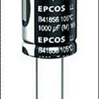
Aluminum Electrolytic Capacitors - Leaded 35volts 470uF 10x16mm 85deg C
Manufacturer
EPCOS Inc
Series
B41827r
Datasheet
1.B41827A5107M000.pdf
(20 pages)
Specifications of B41827A7477M000
Operating Temperature Range
- 40 C to + 85 C
Termination Style
Radial
Dimensions
10 mm Dia. x 16 mm L
Product
General Purpose Electrolytic Capacitors
Load Life
2000 Hrs
Capacitance
470 uF
Tolerance
20 %
Voltage Rating
35 Volts
Lead Spacing
5 mm
Ripple Current
652 mAmps
Lead Free Status / RoHS Status
Lead free / RoHS Compliant
Available stocks
Company
Part Number
Manufacturer
Quantity
Price
Company:

Part Number:
B41827A7477M000
Manufacturer:
EPCOS
Quantity:
30 000


General
Also see “Important notes” on page 20.
1
2
3
4
5
6
7
8
9
10
Please read Cautions and warnings and
Important notes at the end of this document.
Cautions and warnings
Aluminum electrolytic capacitors have a bi-polar structure. This is marked on the body of the
capacitor. A capacitor must not be mounted with reversed polarity. The application of an AC
or reverse voltage may cause a short circuit or damage the capacitor. Bi-polar capacitors
must not be used in AC applications, where the polarity may be reversed in the circuits or is
unknown.
The DC voltage applied to the capacitor terminal must not exceed its rated operating voltage,
as this will result in a rapid increase of the leakage current and may damage the capacitor. It
is recommended to operate the capacitor at 70–80% of its rated voltage to optimize its serv-
ice life.
The ripple current applied to the capacitor must be within the permitted range. An excessive
ripple current leads to impaired electrical properties and may damage the capacitor. Note that
the sum of the peak values of the ripple voltage and the DC operating voltage must not ex-
ceed the rated DC voltage.
Capacitors must be used within their permitted range of operating temperature. Operation at
room temperature optimizes their service life.
Capacitors with case diameter 8 mm are equipped with a safety vent. In capacitors fitted
with a lead or soldering lug, the safety vent is usually located at the base of the case. It needs
sufficient space around it to operate optimally. The following dimensions are recommended:
for case diameter d = 8 to 16 mm, more than 2 mm; for d =18 to 35 mm, more than 3 mm;
and for d = 42 mm or more, more than 5 mm.
Capacitors should not be mounted with the safety vent face down on the board. Do not locate
any wire or copper trace near the safety vent. Do not reverse the voltage, as this may result
in excess pressure and the leakage of electrolyte.
Gas is released through the safety vent when the pressure inside the capacitor is too high. A
gaseous liquid around the safety vent does not indicate a leakage of electrolyte.
The capacitor should be stored under conditions of normal temperature and in a non-acid,
non-alkali environment of normal humidity. Exposure to high temperatures, for example un-
der direct sunlight, will reduce its operating life. If the capacitor is stored in an environment
containing acids or alkalis, the solderability of the leads may be affected.
The leakage current of an aluminum electrolytic capacitor may increase after a long period
of storage. After such storage, the capacitor must be aged by applying the rated operating
voltage for 6–8 hours before use.
Manual soldering:
a Soldering must be performed within the specified conditions.
b Ensure that the soldering iron does not touch any part of the capacitor body.
Bit temperature: 350 C; application time of soldering iron: 3 seconds.
18
08/08
Related parts for B41827A7477M000
Image
Part Number
Description
Manufacturer
Datasheet
Request
R


Part Number:
Description:
CAP .15UF 63V METAL POLY
Manufacturer:
EPCOS Inc
Datasheet:


Part Number:
Description:
CAP .01UF 400V METAL POLY
Manufacturer:
EPCOS Inc
Datasheet:
