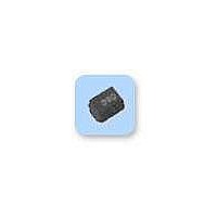
ELJ-EA331KF Panasonic, ELJ-EA331KF Datasheet

ELJ-EA331KF
Manufacturer Part Number
ELJ-EA331KF
Description
Power Inductors 330UH 10% INDUCTOR
Manufacturer
Panasonic
Datasheet
1.ELJ-EA101KF.pdf
(2 pages)
Specifications of ELJ-EA331KF
Test Frequency
0.796 MHz
Inductance
330 uH
Tolerance
20 %
Maximum Dc Current
30 mAmps
Maximum Dc Resistance
7.1 Ohms
Self Resonant Frequency
4 MHz
Q Minimum
20
Dimensions
2.5 mm W x 3.2 mm L x 2.2 mm H
Shielding
Unshielded
Operating Temperature Range
- 20 C to + 85 C
Termination Style
SMD/SMT
Package / Case
1210 (3225 metric)
Lead Free Status / RoHS Status
Lead free / RoHS Compliant
Available stocks
Company
Part Number
Manufacturer
Quantity
Price
Company:
Part Number:
ELJ-EA331KF
Manufacturer:
PANASONIC
Quantity:
84 000
6. Low DC Resistance Type EA
■
● Low DCR, suitable for power circuitry.
● Magnetic shield effect using ferrite mixed outer molding.
● Capable of being Re-fl ow or fl ow soldered.
● Good for mounting.
■
● AV equipment, Wireless communication equipment and various types of general electronic equipment.
■
■ Storage Conditions
● Package
● Operating Temperature : –20 to +85 °C
■ Storage Period
● Solderability may be reduced due to the conditions of high temperature and high humidity which causes the oxidation
■ Packaging
■ Soldering Conditions
■ Safety Precautions
Design and specifi cations are each subject to change without notice. Ask factory for the current technical specifi cations before purchase and/or use.
Should a safety concern arise regarding this product, please be sure to contact us immediately.
Features
Recommended Applications
Explanation of Part Numbers
of tin-plated terminals. Even if storage conditions are within specifi ed limits, solderability may be reduced with the
passage of time. Therefore, please control the storage conditions and try to use the product within 6 months of receipt.
E
Chip Inductors
1
Product code
L
2
: Normal temperature (–5 to 35 °C), normal humidity (85 %RH max.), shall not be exposed to
direct sunlight and harmful gases and care should be taken so as not to cause dew.
J
EA
3
Size : mm (inch)
Refer 27 and 28 page.
Refer 29 page.
Refer 30 page.
3225 (1210)
Type
E
4
A
5
3R3
470
561
Inductance
560 µH
3.3 µH
47 µH
1
6
R
7
Inductance tolerance
K
M
5
8
±10 %
±20 %
Fixed Inductors (Chip Inductors)
K
9
Packaging Design No.
F
10
F
Taping
11
Jul. 2008
Related parts for ELJ-EA331KF
ELJ-EA331KF Summary of contents
Page 1
Low DC Resistance Type EA ■ Features ● Low DCR, suitable for power circuitry. ● Magnetic shield effect using ferrite mixed outer molding. ● Capable of being Re-fl fl ow soldered. ● Good for mounting. ■ Recommended ...
Page 2
... ELJ EA100KF 10 ELJ EA150KF 15 ELJ EA220KF 22 ELJ EA330KF 33 ELJ EA470KF ±10 % ELJ EA680KF 68 ELJ EA101KF 100 ELJ EA151KF 150 ELJ EA221KF 220 ELJ EA331KF 330 ✽1 : Self Resonant Frequency ✽ Resistance Design and specifi cations are each subject to change without notice. Ask factory for the current technical specifi cations before purchase and/or use. ...


