PWC-PWC0805LF-1R00-F IRC, PWC-PWC0805LF-1R00-F Datasheet
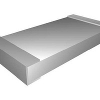
Thick Film Resistors - SMD 1ohm 125milliwatt 0.01

PWC-PWC0805LF-1R00-F

Manufacturer Part Number
PWC-PWC0805LF-1R00-F
Description
Thick Film Resistors - SMD 1ohm 125milliwatt 0.01
Manufacturer
IRC
Datasheet

Specifications of PWC-PWC0805LF-1R00-F

Resistance
1 Ohms
Tolerance
1 %
Power Rating
125 mWatts
Termination Style
SMD/SMT
Package / Case
0805 (2013 metric)
Voltage Rating
150 Volts
Operating Temperature Range
- 55 C to + 155 C
Dimensions
1.25 mm W x 2 mm L x 0.6 mm H
Temperature Coefficient
+/- 200 PPM / C
Lead Free Status / RoHS Status
Lead free / RoHS Compliant
Pulse Withstanding
Chip Resistors
PWC Series
Electrical Data
*Recommended minimum pad and adjacent trace area for each termination for rated power on FR4 PCB.
Environmental Data
General Note
IRC reserves the right to make changes in product specification without notice or liability.
All information is subject to IRC’s own data and is considered accurate at time of going to print.
)Advanced Film Division
Telephone: 361 992 7900 • Facsimile: 361 992 3377 • Website: www.irctt.com
Note
Characteristic
Resistance Range
Power @ 70°C
Max Voltage Rating
Absolute TCR
Operating Temperature
Thermal Impedance
Pad/Trace Area
Termination
Test
Load life at rated power (1000 hours @ 70°C)
Overload (6.25 X rated power for 5 seconds)
High temperature storage (1000 hours @ 155°C)
Moisture resistance
Thermal shock
Resistance to soldering heat
Higher power ratings
Improved working voltage ratings
Excellent pulse withstanding performance
Sn/Pb or Pb-free wrap-around terminations
Standard chip sizes available from 0805 to 2512
1
: 0.01W added for all resistance values <10W.
±1%, ±5%
• 4222 South Staples Street • Corpus Christi Texas 78411 USA
±0.5%
220°C/W
125mW
40mm
150V
0805
2*
Wrap-around Sn/Pb or Pb-free with leach resistant Ni barrier
<10W = ±200ppm; ≥10W = ±100ppm/°C
160°C/W
330mW
50mm
200V
1206
2*
-55°C to +155°C
1.0W to 10MW
10W to 1MW
Maximum
1.00%
1.00%
1.00%
1.00%
0.25%
0.25%
750mW
80°C/W
60mm
400V
2010
1
2*
∆R
Typical ∆R
100mm
50°C/W
0.25%
0.10%
0.20%
0.25%
0.05%
0.05%
1.5W
500V
2512
PWC Series Issue July 2008
2*
TTelectronics plc
A subsidiary of

Related parts for PWC-PWC0805LF-1R00-F

PWC-PWC0805LF-1R00-F Summary of contents

Page 1

... Wrap-around Sn/Pb or Pb-free with leach resistant Ni barrier 2010 2512 750mW 1.5W 400V 500V 80°C/W 50°C/W 60mm 100mm 2* Maximum ∆R Typical ∆R 1 1.00% 0.25% 1.00% 0.10% 1.00% 0.20% 1.00% 0.25% 0.25% 0.05% 0.25% 0.05% PWC Series Issue July 2008 2* A subsidiary of TTelectronics plc ...

Page 2

... Telephone: 361 992 7900 • Facsimile: 361 992 3377 • Website: www.irctt.com 1.2/50 µS Lightning Surge 100 1000 10000 100000 Resistance (ohms) 10/700 µS Lightning Surge 100 1000 10000 100000 Resistance (ohms) 2512 2010 1206 0805 1000000 10000000 2512 2010 1206 0805 1000000 10000000 PWC Series Issue July 2008 ...

Page 3

... Continuous Pulses 100 10 1 0.1 0.0001 0.001 0.01 Pulse Duration (seconds) Pulse Voltage 10000 1000 100 10 0.0001 0.001 0.01 Pulse Duration (seconds) 2512 2010 1206 0805 0.1 1 2512 2010 1206 0805 2512 2010 1206 0805 0.1 1 PWC Series Issue July 2008 ...

Page 4

... Tin (pb-free) termination Resistance Value (Use IEC62 code) 155° Tolerance Code J = ±5 ±1 ±0.5% For additional information or to discuss your specific requirements, please contact our Applications Team using the contact details below PWC - PWC 2512LF - 100R - F PWC Series Issue July 2008 ...

Related keywords