AD22280-R2 Analog Devices Inc, AD22280-R2 Datasheet - Page 8
AD22280-R2
Manufacturer Part Number
AD22280-R2
Description
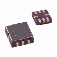
IC ACCELER 50G SNGL-AXIS 8CLCC
Manufacturer
Analog Devices Inc
Series
iMEMS®r
Datasheet
1.AD22279-A-R2.pdf
(12 pages)
Specifications of AD22280-R2
Acceleration Range
±50g
Axis
X or Y
Sensitivity
38mV/g
Voltage - Supply
5V
Output Type
Analog
Bandwidth
400Hz
Mounting Type
Surface Mount
Package / Case
8-CLCC
No. Of Axes
1
Sensor Case Style
LCC
No. Of Pins
8
Supply Voltage Range
4.75V To 5.25V
Operating Temperature Range
-40°C To +105°C
Acceleration Range ±
70gf
Family Name
AD22280
Package Type
CLLCC
Operating Supply Voltage (min)
4.75V
Operating Supply Voltage (typ)
5V
Operating Supply Voltage (max)
5.25V
Operating Temperature (min)
-40C
Operating Temperature (max)
105C
Operating Temperature Classification
Industrial
Product Depth (mm)
5mm
Product Height (mm)
1.98mm
Product Length (mm)
5mm
Mounting
Surface Mount
Pin Count
8
Package
8CLLCC
Acceleration
±50 g
Axis Type
Single
Device Sensitivity Range
36.1 to 39.9 mV/g
Lead Free Status / RoHS Status
Lead free / RoHS Compliant
Interface
-
Lead Free Status / Rohs Status
Compliant
Other names
AD22280-R2TR
Available stocks
Company
Part Number
Manufacturer
Quantity
Price

Part Number:
AD22280-R2
Manufacturer:
ADI/亚德诺
Quantity:
20 000


ADXL78
APPLICATIONS
POWER SUPPLY DECOUPLING
For most applications, a single 0.1 μF capacitor, C
decouples the accelerometer from noise on the power supply.
However, in some cases, particularly where noise is present at
the 400 kHz internal clock frequency (or any harmonic
thereof), noise on the supply can cause interference on the
ADXL78’s output. If additional decoupling is needed, a 50 Ω (or
smaller) resistor or ferrite bead can be inserted in the supply
line. Additionally, a larger bulk bypass capacitor (in the 1 μF to
4.7 μF range) can be added in parallel to C
SELF-TEST
The fixed fingers in the forcing cells are normally kept at the
same potential as that of the movable frame. When the self-test
digital input is activated, the voltage on the fixed fingers on one
side of the moving plate in the forcing cells is changed. This
creates an attractive electrostatic force, which causes the frame
to move toward those fixed fingers. The entire signal channel is
active; therefore, the sensor displacement causes a change in
V
method of verifying the operation of the accelerometer.
Because electrostatic force is independent of the polarity of the
voltage across capacitor plates, a positive voltage is applied in
half of the forcing cells, and its complement in the other half of
the forcing cells. Activating self-test causes a step function force
to be applied to the sensor, while the capacitive coupling term is
canceled. The ADXL78 has improved self-test functionality,
including excellent transient response and high speed switching
capabilities. Arbitrary force waveforms can be applied to the
sensor by modulating the self-test input, such as test signals to
measure the system frequency response or even crash signals to
verify algorithms within the limits of the self-test swing.
The ST pin should never be exposed to voltages greater than
V
design (for instance, if there are multiple supply voltages), then
a low V
CLOCK FREQUENCY SUPPLY RESPONSE
In any clocked system, power supply noise near the clock
frequency may have consequences at other frequencies. An
internal clock typically controls the sensor excitation and the
signal demodulator for micromachined accelerometers.
If the power supply contains high frequency spikes, they may be
demodulated and interpreted as an acceleration signal. A signal
appears as the difference between the noise frequency and the
demodulator frequency. If the power supply spikes are 100 Hz
away from the demodulator clock, there is an output term at
100 Hz. If the power supply clock is at exactly the same frequency
as the accelerometer clock, the term appears as an offset.
OUT
S
+ 0.3 V. If this cannot be guaranteed due to the system
. The ADXL78 self-test function is a comprehensive
F
clamping diode between ST and V
DC
S
.
is recommended.
DC
, adequately
Rev. B | Page 8 of 12
If the difference frequency is outside of the signal bandwidth,
the filter attenuates it. However, both the power supply clock
and the accelerometer clock may vary with time or temperature,
which can cause the interference signal to appear in the output
filter bandwidth.
The ADXL78 addresses this issue in two ways. First, the high
clock frequency eases the task of choosing a power supply clock
frequency such that the difference between it and the accelero-
meter clock remains well outside of the filter bandwidth.
Second, the ADXL78 is the only micromachined accelerometer
to have a fully differential signal path, including differential
sensors. The differential sensors eliminate most of the power
supply noise before it reaches the demodulator. Good high
frequency supply bypassing, such as a ceramic capacitor close to
the supply pins, also minimizes the amount of interference.
The clock frequency supply response (CFSR) is the ratio of the
response at V
accelerometer clock frequency. A CFSR of 3 means that the
signal at V
near the accelerometer internal clock frequency. This is
analogous to the power supply response, except that the
stimulus and the response are at different frequencies. The
ADXL78’s CFSR is 10× better than a typical single-ended
accelerometer system.
SIGNAL DISTORTION
Signals from crashes and other events may contain high
amplitude, high frequency components. These components
contain very little useful information and are reduced by the
2-pole Bessel filter at the output of the accelerometer. However,
if the signal saturates at any point, the accelerometer output
does not look like a filtered version of the acceleration signal.
The signal may saturate anywhere before the filter. For example,
if the resonant frequency of the sensor is low, the displacement
per unit acceleration is high. The sensor may reach the
mechanical limit of travel if the applied acceleration is high
enough. This can be remedied by locating the accelerometer
where it does not see high values of acceleration, and by using a
higher resonant frequency sensor such as the ADXL78.
Also, the electronics may saturate in an overload condition
between the sensor output and the filter input. Ensuring that
the internal circuit nodes operate linearly to at least several
times the full-scale acceleration value can minimize electrical
saturation. The ADXL78’s circuits are linear to approximately
8× full scale.
OUT
OUT
is 3× the amplitude of an excitation signal at V
to the noise on the power supply near the
DD
Related parts for AD22280-R2
Image
Part Number
Description
Manufacturer
Datasheet
Request
R

Part Number:
Description:
±1.7g Dual-Axis IMEMS Accelerometer Evaluation Board
Manufacturer:
Analog Devices Inc
Datasheet:

Part Number:
Description:
Inertial Sensor Evaluation System
Manufacturer:
Analog Devices Inc
Datasheet:
Part Number:
Description:
Manufacturer:
Analog Devices Inc
Datasheet:
Part Number:
Description:
Manufacturer:
Analog Devices Inc
Datasheet:
Part Number:
Description:
Manufacturer:
Analog Devices Inc
Datasheet:
Part Number:
Description:
Manufacturer:
Analog Devices Inc
Datasheet:
Part Number:
Description:
Manufacturer:
Analog Devices Inc
Datasheet:
Part Number:
Description:
Manufacturer:
Analog Devices Inc
Datasheet:
Part Number:
Description:
Manufacturer:
Analog Devices Inc
Datasheet:
Part Number:
Description:
Manufacturer:
Analog Devices Inc
Datasheet:
Part Number:
Description:
Manufacturer:
Analog Devices Inc
Datasheet:
Part Number:
Description:
Manufacturer:
Analog Devices Inc
Datasheet: