ADXL103CE Analog Devices Inc, ADXL103CE Datasheet - Page 4
ADXL103CE
Manufacturer Part Number
ADXL103CE
Description
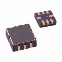
IC ACCELEROMETER SNGL-AXIS 8CLCC
Manufacturer
Analog Devices Inc
Series
iMEMS®r
Specifications of ADXL103CE
Acceleration Range
±1.7g
Axis
X or Y
Sensitivity
1000mV/g
Voltage - Supply
3 V ~ 6 V
Output Type
Analog
Bandwidth
1Hz ~ 500Hz Selectable
Mounting Type
Surface Mount
Package / Case
8-CLCC
No. Of Axes
1
Sensor Case Style
LCC
No. Of Pins
8
Supply Voltage Range
3V To 6V
Operating Temperature Range
-40°C To +125°C
Msl
MSL 1 - Unlimited
Sensitivity Per Axis
1000mV / G
Svhc
No
Rohs Compliant
Yes
Lead Free Status / RoHS Status
Lead free / RoHS Compliant
Interface
-
Lead Free Status / RoHS Status
Lead free / RoHS Compliant, Lead free / RoHS Compliant
Available stocks
Company
Part Number
Manufacturer
Quantity
Price
Company:

Part Number:
ADXL103CE
Manufacturer:
QUALCOMM
Quantity:
2
Company:
Part Number:
ADXL103CE
Manufacturer:
AD
Quantity:
4 130
Part Number:
ADXL103CE
Manufacturer:
ADI/亚德诺
Quantity:
20 000
Part Number:
ADXL103CE-REEL
Manufacturer:
ADI/亚德诺
Quantity:
20 000
Company:
Part Number:
ADXL103CEREEL
Manufacturer:
VISHAY
Quantity:
4 366


ADXL103/ADXL203
ABSOLUTE MAXIMUM RATINGS
Table 2.
Parameter
Acceleration (Any Axis, Unpowered)
Acceleration (Any Axis, Powered)
Drop Test (Concrete Surface)
V
All Other Pins
Output Short-Circuit Duration
Temperature Range (Powered)
Temperature Range (Storage)
ESD CAUTION
ESD (electrostatic discharge) sensitive device. Electrostatic charges as high as 4000 V readily accumulate on the
human body and test equipment and can discharge without detection. Although this product features
proprietary ESD protection circuitry, permanent damage may occur on devices subjected to high energy
electrostatic discharges. Therefore, proper ESD precautions are recommended to avoid performance
degradation or loss of functionality.
S
(Any Pin to Common)
Minimum Temperature (T
Maximum Temperature (T
Time (T
Profile Feature
Average Ramp Rate (T
Preheat
T
Time Maintained above Liquidous (T
Liquidous Temperature (T
Peak Temperature (T
Time Within 5°C of Actual Peak Temperature (t
Ramp-Down Rate
Time 25°C to Peak Temperature
Ramp-Up Rate
Time (t
SMAX
to T
L
SMIN
L
)
T
T
P
L
to T
T
3500 g
Rating
3500 g
1.2 m
−0.3 V to +7.0 V
(COM − 0.3 V) to
(V
Indefinite
−55°C to +125°C
−65°C to +150°C
SMIN
T
SMAX
S
SMAX
+ 0.3 V)
P
) (t
)
L
to T
S
)
Figure 2. Recommended Soldering Profile
PREHEAT
P
)
SMIN
L
SMAX
)
t
25°C TO PEAK
t
S
)
)
Rev. C | Page 4 of 12
L
)
RAMP-UP
TIME
P
)
RAMP-DOWN
Stresses above those listed under Absolute Maximum Ratings
may cause permanent damage to the device. This is a stress
rating only; functional operation of the device at these or any
other conditions above those indicated in the operational
section of this specification is not implied. Exposure to absolute
maximum rating conditions for extended periods may affect
device reliability.
Table 3. Package Characteristics
Package Type
8-Lead CLCC
Sn63/Pb37
100°C
150°C
60 to 120 seconds
183°C
60 to 150 seconds
240°C + 0°C/−5°C
6 minutes max
10 to 30 seconds
t
P
t
L
3°C/second max
6°C/second max
CRITICAL ZONE
3°C/second
Condition
T
L
TO T
Pb-Free
150°C
200°C
60 to 150 seconds
217°C
60 to 150 seconds
260°C + 0°C/−5°C
8 minutes max
20 to 40 seconds
θ
120°C/W
P
JA
θ
20°C/W
JC
Device Weight
<1.0 gram
Related parts for ADXL103CE
Image
Part Number
Description
Manufacturer
Datasheet
Request
R

Part Number:
Description:
±1.7g Dual-Axis IMEMS Accelerometer Evaluation Board
Manufacturer:
Analog Devices Inc
Datasheet:

Part Number:
Description:
Inertial Sensor Evaluation System
Manufacturer:
Analog Devices Inc
Datasheet:
Part Number:
Description:
Manufacturer:
Analog Devices Inc
Datasheet:
Part Number:
Description:
Manufacturer:
Analog Devices Inc
Datasheet:
Part Number:
Description:
Manufacturer:
Analog Devices Inc
Datasheet:
Part Number:
Description:
Manufacturer:
Analog Devices Inc
Datasheet:
Part Number:
Description:
Manufacturer:
Analog Devices Inc
Datasheet:
Part Number:
Description:
Manufacturer:
Analog Devices Inc
Datasheet:
Part Number:
Description:
Manufacturer:
Analog Devices Inc
Datasheet:
Part Number:
Description:
Manufacturer:
Analog Devices Inc
Datasheet:
Part Number:
Description:
Manufacturer:
Analog Devices Inc
Datasheet:
Part Number:
Description:
Manufacturer:
Analog Devices Inc
Datasheet:
Part Number:
Description:
Manufacturer:
Analog Devices Inc
Datasheet: