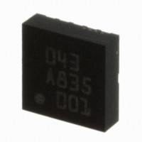
BMA150 Bosch Sensortec, BMA150 Datasheet - Page 51

BMA150
Manufacturer Part Number
BMA150
Description
3-AXIS ACCELEROMETER DIGITAL I/F
Manufacturer
Bosch Sensortec
Specifications of BMA150
Axis
X, Y, Z
Acceleration Range
± 2g, 4g, 8g
Sensitivity
256LSB/g, 128LSB/g, 64LSB/g
Voltage - Supply
2.4 V ~ 3.6 V
Output Type
Digital
Bandwidth
3kHz
Interface
I²C, SPI
Mounting Type
Surface Mount
Package / Case
12-LGA
For Use With
DM180021 - KIT STARTER MPLAB FOR PIC18F MCU828-1013 - BMA150 TRIBOX DEMO BOARD W/USB828-1009 - BMA150 DAUGHTERCARD FOR DEV KIT
Lead Free Status / RoHS Status
Lead free / RoHS Compliant
Other names
0273 141 043
828-1003-2
828-1003-2
Available stocks
Company
Part Number
Manufacturer
Quantity
Price
Company:
Part Number:
BMA150
Manufacturer:
BOSCH
Quantity:
5 888
Part Number:
BMA150
Manufacturer:
BOSCH/博世
Quantity:
20 000
8. Data conversion
8.1 Acceleration data
Acceleration data are converted by a 10bit ADC. The description of the digital signal is "2’s
complement". The 10 bit data are available as LSB (at lower register address) and MSB. It is
possible to read out MSB only (8 bit) and LSB/MSB (16 bits with 10 data bits and 1 data ready
bit) while LSB- and MSB-data are closely linked to avoid unintentional LSB/MSB mixing when
read out and data conversion overlap accidentally (section 3.5.2).
The update rate of data registers is 3 kHz, independent of the digital filter. The acceleration data
is filtered by a second order analog filter at 1.5 kHz. Additionally the data can be processed by
digital averaging filters (moving average) to reduce the noise level (750Hz – 25Hz).
The transfer function of the mechanical element is designed to avoid resonance effects at
frequencies below the bandwidth of the ASIC.
The availability of new data can be checked in two ways:
•
•
Figure 29: Explanation of data ready interrupt: For a bandwidth of e.g. 1.5 kHz the data refresh
cycle takes 330µs to update all data registers. After the final conversion of z-axis the INT pad
will be set high. New data can be read out via interface (recommendation: read out within 20µs
after interrupt is high during the conversion of the next temperature value). The interrupt resets
automatically after read out.
8.2 Temperature measurement
Temperature data are converted to an 8bit data register. The temperature output range can be
adapted to customer’s requirements by offset correction.
Rev. 1.6
© Bosch Sensortec GmbH reserves all rights even in the event of industrial property rights. We reserve all rights of disposal such
as copying and passing on to third parties. BOSCH and the symbol are registered trademarks of Robert Bosch GmbH, Germany.
Note: Specifications within this document are subject to change without notice.
Bit 0 from the LSB data registers is an indicator whether the data have already been
read out or the data are new (Bit0=1) (section 3.5.3).
The interrupt pin can be configured to indicate new data availability (not possible in
parallel to internal interrupt logic). The synchronization of data acquisition and data read
out enables the customer to avoid unnecessary interface traffic in order to reduce the
system power consumption and the crosstalk between interface communication and data
conversion. For a detailed explanation see Figure 23. (section 3.2.10)
INT
INT
INT
T
T
T
330µs at bw=1.5kHz
330µs at bw=1.5kHz
X
X
X
Triaxial, digital acceleration sensor
Y
Y
Y
Data sheet
BMA150
Page 51
Z
Z
Z
T
T
T
X
X
X
Y
Y
Y
Z
Z
Z
Bosch Sensortec
30 October 2008


