ADXL210AE-REEL Analog Devices Inc, ADXL210AE-REEL Datasheet - Page 11
ADXL210AE-REEL
Manufacturer Part Number
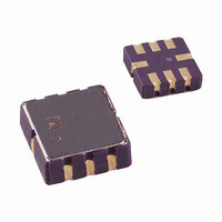
ADXL210AE-REEL
Description
IC ACCELEROMETER LP 8-CLCC
Manufacturer
Analog Devices Inc
Datasheet
1.ADXL210EB.pdf
(12 pages)
Specifications of ADXL210AE-REEL
Axis
X, Y
Acceleration Range
±10g
Sensitivity
100mV/g
Voltage - Supply
3 V ~ 5.25 V
Output Type
Analog
Bandwidth
6kHz
Mounting Type
Surface Mount
Package / Case
8-CLCC
Lead Free Status / RoHS Status
Lead free / RoHS Compliant
Interface
-


Table V. Trade-Offs Between Microcontroller Counter Rate,
T2 Period, and Resolution of Duty Cycle Modulator
T2 (ms) (k ) Rate
1.0
1.0
1.0
5.0
5.0
5.0
10.0
10.0
10.0
USING THE ANALOG OUTPUT
The ADXL210E was specifically designed for use with its digital
outputs, but has provisions to provide analog outputs as well.
Duty Cycle Filtering
An analog output can be reconstructed by filtering the duty cycle
output. This technique requires only passive components. The
duty cycle period (T2) should be set to <1 ms. An RC filter with a
3 dB point at least a factor of >10 less than the duty cycle fre-
quency is connected to the duty cycle output. The filter resistor
should be no less than 100 kΩ to prevent loading of the output
stage. The analog output signal will be ratiometric to the supply
voltage. The advantage of this method is an output scale factor of
approximately double the analog output. Its disadvantage is that
the frequency response will be lower than when using the X
Y
X
The second method is to use the analog output present at the
X
output impedance and are not designed to drive a load directly.
An op amp follower may be required to buffer this pin. The
advantage of this method is that the full 5 kHz bandwidth of the
accelerometer is available to the user. A capacitor still must be
added at this point for filtering. The duty cycle converter should
be kept running by using R
ometer offset and sensitivity are ratiometric to the supply voltage.
The offset and sensitivity are nominally:
USING THE ADXL210E IN VERY LOW POWER
APPLICATIONS
An application note outlining low power strategies for the
ADXL210E is available. Some key points are presented here.
It is possible to reduce the ADXL210E’s average current from
0.6 mA to less than 20 µA by using the following techniques:
1. Power cycle the accelerometer.
2. Run the accelerometer at a lower voltage (down to 3 V).
FILT
FILT
FILT
, Y
output.
and Y
FILT
R
124
124
124
625
625
625
1250 100
1250 100
1250 100
SET
ADXL210E Sensitivity = (20 mV
Output
FILT
ADXL210E Clock
Sample
1000
1000
1000
200
200
200
pin. Unfortunately, these pins have a 32 kΩ
0 g Offset = V
Counter-
Rate
(MHz)
2.0
1.0
0.5
2.0
1.0
0.5
2.0
1.0
0.5
SET
<10 MΩ. Note that the acceler-
DD
Counts
per T2
Cycle
2000
1000
500
10000
5000
2500
20000
10000
5000
/2
Counts Resolution
per g
80
40
20
400
200
100
800
400
200
V
S
)/g
(mg)
12.50
25.00
50.00
2.50
5.00
10.00
1.25
2.50
5.00
FILT
,
Power Cycling with an External A/D
Depending on the value of the X
is capable of turning on and giving a good reading in 1.6 ms.
Most microcontroller-based A/Ds can acquire a reading in
another 25 µs. Thus it is possible to turn on the ADXL210E
and take a reading in <2 ms. If we assume that a 20 Hz sample
rate is sufficient, the total current required to take 20 samples is:
Running the part at 3 V will reduce the supply current from
0.6 mA to 0.4 mA, bringing the average current down to 16 µA.
The A/D should read the analog output of the ADXL210E at
the X
may be required in any case to amplify the analog output to give
enough resolution with an 8-bit to 10-bit converter.
Power Cycling When Using the Digital Output
An alternative is to run the microcontroller at a higher clock rate
and put it into shutdown between readings, allowing the use of the
digital output. In this approach the ADXL210E should be set at
its fastest sample rate (T2 = 0.5 ms), with a 500 Hz filter at X
and Y
possible and then shut down the ADXL210E and the microcon-
troller until the next sample is needed.
In either of the above approaches, the ADXL210E can be turned
on and off directly using a digital port pin on the microcontroller to
power the accelerometer without additional components.
CALIBRATING THE ADXL210E
The initial value of the offset and scale factor for the ADXL210E will
require calibration for applications such as tilt measurement. The
ADXL210E architecture has been designed so that these calibra-
tions take place in the software of the microcontroller used to decode
the duty cycle signal. Calibration factors can be stored in EEPROM
or determined at turn-on and saved in dynamic memory.
For low g applications, the force of gravity is the most stable,
accurate and convenient acceleration reference available. A reading
of the 0 g point can be determined by orientating the device
parallel to the earth’s surface and then reading the output.
A more accurate calibration method is to make measurements at
+1 g and –1 g. The sensitivity can be determined by the two
measurements.
To calibrate, the accelerometer’s measurement axis is pointed
directly at the earth. The 1 g reading is saved and the sensor is
turned 180° to measure –1 g. Using the two readings, the sensi-
tivity is:
For example, if the +1 g reading (A) is 55% duty cycle and the
–1 g reading (B) is 47% duty cycle, then:
These equations apply whether the output is analog or duty cycle.
Application notes outlining algorithms for calculating accelera-
tion from duty cycle and automated calibration routines are
available from the factory.
Let B = Accelerometer output with axis oriented to –1 g then:
FILT
FILT
Let A = Accelerometer output with axis oriented to +1 g
and Y
. The concept is to acquire a reading as quickly as
2 ms
Sensitivity = [55% – 47%]/2 g = 4%/g
FILT
20 Samples/s
pins. A buffer amplifier is recommended, and
Sensitivity = [A – B]/2 g
FILT
0.6 mA = 24 µA
capacitor, the ADXL210E
ADXL210E
FILT
Related parts for ADXL210AE-REEL
Image
Part Number
Description
Manufacturer
Datasheet
Request
R

Part Number:
Description:
IC ACCELEROMETER LP 8-CLCC
Manufacturer:
Analog Devices Inc
Datasheet:

Part Number:
Description:
±1.7g Dual-Axis IMEMS Accelerometer Evaluation Board
Manufacturer:
Analog Devices Inc
Datasheet:

Part Number:
Description:
Inertial Sensor Evaluation System
Manufacturer:
Analog Devices Inc
Datasheet:
Part Number:
Description:
Manufacturer:
Analog Devices Inc
Datasheet:
Part Number:
Description:
Manufacturer:
Analog Devices Inc
Datasheet:
Part Number:
Description:
Manufacturer:
Analog Devices Inc
Datasheet:
Part Number:
Description:
Manufacturer:
Analog Devices Inc
Datasheet:
Part Number:
Description:
Manufacturer:
Analog Devices Inc
Datasheet:
Part Number:
Description:
Manufacturer:
Analog Devices Inc
Datasheet:
Part Number:
Description:
Manufacturer:
Analog Devices Inc
Datasheet:
Part Number:
Description:
Manufacturer:
Analog Devices Inc
Datasheet:
Part Number:
Description:
Manufacturer:
Analog Devices Inc
Datasheet:
Part Number:
Description:
Manufacturer:
Analog Devices Inc
Datasheet: