5693 Anderson Power Products, 5693 Datasheet - Page 85
5693
Manufacturer Part Number
5693
Description
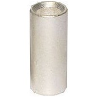
BUSHING, 6384G1 CONTACT
Manufacturer
Anderson Power Products
Series
PP180, SB175, SBE160, SBE320, SBX175, Contactsr
Datasheet
1.5693.pdf
(96 pages)
Specifications of 5693
Leaded Process Compatible
No
Accessory Type
Reducing Bushing
For Use With
1382, 944, 6384G1, 6354 & 6384G1 Contacts
Lead Free Status / RoHS Status
Lead free / RoHS Compliant
Lead Free Status / RoHS Status
Lead free / RoHS Compliant


Anderson Power Products
TAIWAN: IDEAL Anderson Asia Pacific Ltd., Taiwan Branch, 4F.-2, No.116, Dadun 20th St., Situn District, Taichung City 407, Taiwan (R.O.C.) T: 886-4-2310-6451 F:886-4-2310-6460
CHINA: IDEAL Anderson Technologies (Shenzhen) Ltd., Block A8 Tantou W. Ind. Par, Songgang Baoan District, Shenzhen, PR. China 51810 T: 86-755-2768-2118 F: 86-755-2768-2218
Temperature Rise Curves
A) Reading the Chart:
Temperature rise charts show the associated heat rise as a result of
applied current to the connector. Heat rise is expressed as a ∆T°C.
T ambient- T (maximum w/ applied current)= ∆T The chart on the right
shows the heat rise curve for the PP30 connector. Separate curves are
shown for #16, #14 and #12 AWG wire. Interpreting the curves, if 17
amps is applied continuously to the connector, the heat rise will be 23°C
for #16, 13°C for #14, and 9°C for #12 wire.
B) Ambients and Maximum Operating Temperature:
Connector devices are rated or derated by the wiring configuration and
the environment. Factors to be considered are the wire enclosure
characteristics, connector housing and wire insulation characteristics,
the number of wires in an enclosed area such as a raceway, and the
ambient operating temperatures.
The housing and wire insulation limits are specified by UL and are the
limiting factor in determining the suitability of an application. The
following guidelines should be met:
T°C (ambient) + ∆T°C (at applied current) < T°C (connector) and T°C
(wire insulation) where T°C (connector) = temperature limit of the
connector housing and T°C (wire insulation)= the temperature limit of the
wire insulation.
For example: A two pole PP30 connection with #14AWG wire operating
at 17 amps with an ambient of 35°C. The temperature rise for the
connection is 13°C. 35°C + 13°C= 48°C. The wire insulation is rated to
65°C, the connector housing is rated to a maximum temperature of
105°C. Both temperature limits are below 48°C, therefore, this applica-
tion is suitable.
Pulse Current Curves
Pulse current curves shows the highest instantaneous current that can
be applied to a mated connection. Specifically, these curves show the
time to produce a 30 °C temperature rise. These curves should be
used as a guide in applications that have non-continuous/constant
current.
The curve shown (on the right) is the pulse current curve for a multipole
configuration of the SB50 connector. Interpreting the curves, if 120
amps is applied as a pulse current in an application, the maximum time
that current can be applied will be 1s for #12, 2s for #10, 5s for #8 and
12s for #6 wire.
ASIA/PACIFIC: IDEAL Anderson Asia Pacific Ltd., Unit 922-928 Topsail Plaza, 11 On Sum Street, Shatin N.T., Hong Kong
®
HEADQUARTERS: 13 Pratts Junction Road, P.O. Box 579, Sterling, MA 01564 T:978-422-3600 F:978-422-3700
TEMPERATURE RISE & PULSE CURRENT CHARTS
EUROPE: Rathealy Road, Fermoy Co. Cork, Ireland
www.andersonpower.com
40
30
20
10
280
260
240
220
200
180
160
140
120
100
0
80
60
40
20
0
0
T:353-(0)25-32277
0.5
5
1
Temperature Rise at Constant Current
10
2
Duration of Current (seconds)
Pulse Current Capability
15
PP30 Singlepole
4
Interpretation
Amperes Applied
F:353-(0)25-32296
8
20
SB50
16
25
32
T:852-2636-0836
30
64
128 256
35
of Charts
F:852-2635-9036
40
12 AWG
14 AWG
16 AWG
10 AWG
12 AWG
6 AWG
8 AWG
- 83 -
Related parts for 5693
Image
Part Number
Description
Manufacturer
Datasheet
Request
R

Part Number:
Description:
Bushing for use with 944 contacts 1/0 to #4 AWG
Manufacturer:
Anderson Power Products
Datasheet:
Part Number:
Description:
ANDERSON POWER PRODUCTS® 1367G1 PNEUMATIC CRIMP TOOL
Manufacturer:
Anderson Power Products
Part Number:
Description:
Manual Crimping Tool For Anderson Power Products Modular Power Connectors
Manufacturer:
Anderson Power Products
Part Number:
Description:
Manual Crimping Tool For Anderson Power Products Modular Power Connectors
Manufacturer:
Anderson Power Products
Part Number:
Description:
Heavy Duty Power Connectors ANDERSON 36/48V AR BCI PRO
Manufacturer:
Anderson Power Products
Part Number:
Description:
Quick Disconnect Terminal: 6.86: M: Silver Over Nickel
Manufacturer:
Anderson Power Products
Part Number:
Description:
PP15/45 2X2 HSG. BLK.BONDED
Manufacturer:
Anderson Power Products