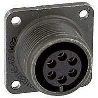
88-569761-98S Amphenol, 88-569761-98S Datasheet - Page 6

88-569761-98S
Manufacturer Part Number
88-569761-98S
Description
CIRCULAR CONN, RCPT, SIZE 9, 3POS, PANEL
Manufacturer
Amphenol
Series
MIL-DTL-38999 Series IIIr
Datasheet
1.88-569761-35P.pdf
(53 pages)
Specifications of 88-569761-98S
Gender
Receptacle
Contact Gender
Socket
Connector Mounting
Panel
Connector Shell Size
9
Insert Arrangement
9-98
Connector Type
Circular Industrial
Guide to Selecting a PCB Cylindrical
Connector
The connector selection process is one of the most important engineering deci-
sions to be made in any electronic application. Amphenol has created this cat-
alog specifically to provide the necessary information to select, layout and
design both the appropriate Amphenol
tacts and the connector footprint (contact locations) on the printed circuit
board. The guide that follows is for application of cylindrical connectors on rigid
printed circuit boards and also applies if a flex print assembly or other optional
is being used.
Engineers working on those PCB or flex print applications requiring rectangular
connectors are encouraged to refer to page 46-48 and ask for Amphenol Rect-
angular Product catalogs.
How To Select a Cylindrical Connector for a PCB Application
The data provided in this catalog is based on three cylindrical connector series:
MIL-DTL-38999 Series I, II and III, MIL-C-26482 Series 1, and MIL-C-5015.
See page 1 for electrical and environmental features and differences of these
three series. The “hot” side of the application determines the choice of pin or
socket genders of the contacts.
How to Measure the PCB Tail Length
The tail length of the PCB is the portion of the contact that extends beyond the
rear of the shell. This length will vary in relationship to the mounting flange,
depending on the series of connector selected. Standard lengths are shown on the connector shell style
drawings in this
catalog. These shell style drawing pages also provide how to order part numbering for standard PCB cylin-
drical connectors.
When computing the desired tail length, it is important to take into consideration the following factors:
Would Alignment Discs, Headers or
Special Stand-off Shells be Beneficial?
Any mechanical methods needed to stabilize the
board or flex to the connector and/or the panel.
The PCB tails shown in this catalog are of one
diameter. Stepped tails or PCB tails with an
increased diameter on a designated portion may
be required for certain applications.
Alignment discs are available which provide ease
of alignment of pins to boards, protection during
shipment and optimized electrical circuit separa-
tion. Header assemblies (see pages 44 & 45) are
available which provide time and cost saving
potentials. Standoffs may be required for certain
applications. Amphenol has developed a new
stand-off adapter (see page 40) which may elimi-
nate the need for special stand-off shell designs.
Connectors with clinch nuts can be provided.
Please call Amphenol to discuss any optional
designs or any special requirements.
• The connector series and shell style.
• The mounting style of the receptacle; jam nut (D hole) or panel mount (four holes).
• The extension of the tail beyond the opposite side of the board or the flex.
• The space required to adequately clean flux from between the board or flex and the rear
This can affect the overall length of the tail.
of the connector shell. Connectors that are mounted flush against the board may trap
soldering flux which could lead to corrosion of the solder joints.
®
cylindrical connector with PCB con-
Special Design with Longer PC Tails in
a 38999 Composite Shell Connector.
Also shows an Alignment Disc.
2
Universal Header Assemblies are available
for Flex Print/PC Board Mounting. Beneficial
especially when electrical testing of the con-
nector requires it to be removed and reat-
tached.
Stand-off Adapter on a Jam Nut
Receptacle.


