MS3102A20-4S Amphenol Industrial Operations, MS3102A20-4S Datasheet - Page 68
MS3102A20-4S
Manufacturer Part Number
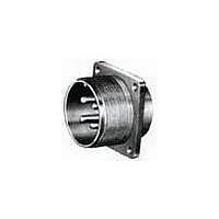
MS3102A20-4S
Description
CIRCULAR CONN, RCPT, SIZE 20, 4POS, BOX
Manufacturer
Amphenol Industrial Operations
Type
Panel Socketr
Specifications of MS3102A20-4S
Connector Body Material
Aluminum Alloy
Gender
Receptacle
Contact Gender
Socket
Connector Mounting
Box
Connector Shell Size
20
Insert Arrangement
20-4
Connector Type
Circular Military
Angle
Straight
Application
True MIL
Brand/series
MS Series
Class
A
Contact Configuration
4#12
Contact Plating
Silver
Contact Type
Socket
Current, Rating
23 A
Diameter, Mounting Hole
0.12 "
Finish, Housing
Olive Drab Cadmium
Housing Type
Metal
Material, Dielectric
Neoprene
Material, Housing
Aluminum Alloy
Mating Type
Threaded
Mount Method
Front
Mounting Type
Flanged
Number Of Contacts
4
Primary Type
5015 MIL Spec
Shell Size
20
Special Features
Single Key/Keyway Shell Polarization
Strain Relief
Solid
Termination
Solder
Voltage, Rating
900/1250 VAC/VDC
Wire, Awg
12
Lead Free Status / RoHS Status
Contains lead / RoHS non-compliant


MS/Standard
solder contacts
Machined copper alloy contacts in a full range of sizes, with closed
entry socket design in the size 12 and 16 contacts. A heavy silver-
plated finish is deposited on all MS style solder contacts for maximum
corrosion resistance, maximum current carrying capacity and low milli-
volt drop.
** Contact ratings as stated are test ratings only. The connector could not with-
† The 10SL, 12S, 14S and 16S connectors require short contacts.
** No attempt has been made to recommend operating voltages. The designer must determine his own
* Solder Wells Filled
† Not corrected for changes in density due to variations in temperature.
10-40569
10-597107-161
10-40599
10-597107-171
10-33646
10-597107-131
10-35531
10-35532
10-35529
10-35530
10-35527
10-35528
stand full rated current through all contacts continuously. Please note that the
electrical data given is not an establishment of electrical safety factors. This is
left entirely in the designer’s hands as he can best determine which peak volt-
age, switching surges, transients, etc. can be expected in a particular circuit.
operating voltage by the application of a safety factor to the above derating chart to compensate for cir-
cuit transients, surges, etc.
Service
Rating
Inst.
A
D
E
B
C
Number
MS
Part
MS/STANDARD SOLDER CONTACTS*
Airspace
Pin
Socket
Pin
Socket
Pin
Socket
Pin
Socket
Pin
Socket
Pin
Socket
1/32
1/16
1/8
3/16
1/4
5/16
Socket
Pin/
Distance
Nominal
16 Long
Short†
Mating
Size
End
16
12
8
4
0
Creepage
1/16
1/8
3/16
1/4
5/16
1
Barrel
Wire
Size
16
16
12
8
4
0
ALTITUDE VOLTAGE DERATING** CHART
Allowable
Wire
Size
Flashover
AC (RMS)
Minimum
16
18
20
22
16
18
20
22
12
14
10
Voltage
8
4
6
0
1
2
1400
2800
3600
4500
5700
8500
Level Conditions
Standard Sea
Current**
Amps
Test
150
125
100
13
10
13
10
23
17
46
33
80
60
7.5
7.5
5
5
AC (RMS)
TABLE II
Voltage
1000
2000
2800
3500
4500
7000
Test
67
* The values listed in Table I represent operating values which include a
generous safety factor. It may be necessary for some applications to
exceed the operating voltages listed here. If this is necessary, designers
will find Table II useful for determining the degree to which the recom-
mended values of Table I can be exceeded.
Service
Rating
CONTACT ARRANGEMENT SERVICE RATING
Flashover
AC (RMS)
Minimum
Inst.
A
D
E
B
C
MS
Voltage
1000
1100
1300
500
800
900
Pressure Altitude†
50,000 Feet
1250
1750
2450
4200
Operating Voltage*
250
700
DC
Recommended
at Sea Level
AC (RMS)
Voltage
Test
400
600
675
750
825
975
TABLE I
AC (RMS)
1250
1750
3000
200
500
900
Flashover
AC (RMS)
Minimum
Voltage
325
450
500
550
600
700
Creepage
Pressure Altitude†
Effective
Distance
Nom.
1/16
1/8
3/16
1/4
5/16
1
70,000 Feet
AC (RMS)
Mechanical
Voltage
Spacing
Test
Nom.
1/16
1/8
3/16
1/4
5/16
260
360
400
440
480
560
Related parts for MS3102A20-4S
Image
Part Number
Description
Manufacturer
Datasheet
Request
R

Part Number:
Description:
CIRCULAR CONN RCPT, SIZE 10SL, 2POS, BOX
Manufacturer:
Amphenol Industrial Operations
Datasheet:

Part Number:
Description:
3 Amp Schottky Rectifier
Manufacturer:
MICROSEMI [Microsemi Corporation]
Datasheet:

Part Number:
Description:
AMPHENOL
Manufacturer:
Amphenol Industrial Operations
Datasheet:

Part Number:
Description:
CIRCULAR INSERT, PIN, 2WAY, SOLDER
Manufacturer:
Amphenol Industrial Operations
Datasheet:

Part Number:
Description:
JAM NUT CONN, RCPT, SIZE 9, 6POS, PANEL
Manufacturer:
Amphenol Industrial Operations
Datasheet:
Part Number:
Description:
PT 41C 41#20 PIN RECP
Manufacturer:
Amphenol Industrial Operations
Part Number:
Description:
PT 41C 41#20 SKT RECP
Manufacturer:
Amphenol Industrial Operations