97-12S-3S Amphenol Industrial Operations, 97-12S-3S Datasheet - Page 9
97-12S-3S
Manufacturer Part Number
97-12S-3S
Description
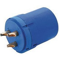
CIRCULAR INSERT, SOCKET, 2WAY, SOLDER
Manufacturer
Amphenol Industrial Operations
Type
Insert Socketr
Specifications of 97-12S-3S
Connector Type
Circular Industrial
Insert Arrangement
12S-3
No. Of Contacts
2
Connector Shell Size
12S
Contact Gender
Socket
Agency Approvals
CSA, UL
Brand/series
97 Series
Contact Mating Area Plating
Silver
Contact Plating
Silver
Contact Type
Socket
Current, Rating
13 A (#16) A
Finish, Housing Test
Olive Drab Cadmium
Gender
Female
Insert Style
Machine Contact
Material, Dielectric
Diallyl-Phthalate
Material, Housing
Aluminum Alloy
Number Of Contacts
2
Number Of Poles
2 (#16 AWG)
Pin Spacing
1/16 "
Primary Type
Industrial
Shell Size
12S
Standards
UL Recognized, CSA Certified
Temperature, Operating
-55 to +125 °C
Termination
Solder
Voltage, Rating
500/700 VAC/VDC
Wire, Awg
#16
Contact Termination
Solder
Rohs Compliant
No
For Use With
Amphenol 97 Series Circular Connectors
Lead Free Status / RoHS Status
Contains lead / RoHS non-compliant


97 series solder type
insert arrangements, cont.
Front view of pin insert or rear of socket insert illustrated.
4 Contacts
5 Contacts
MIL-SPEC SERVICE RATING
Limiting Operating
Voltages at Sea Level
See notes 1 and 2 under TEST CURRENT.
INST. service normally for low voltage and currents.
Effective Creepage (nominal)
Mechanical Spacing (nominal)
† Inactive for new military design, but available for replacement or for
* “MS” number not assigned. Use “97” prefix in place of “MS” in completing
non-military purposes.
catalog number. See how to order, page 19.
Insert Arrangement
Contacts
Service Rating
Insert Arrangement
Contacts
Service Rating
Insert Arrangement
Contacts
Service Rating
Insert Arrangement
Contacts
Service Rating
Items highlighted are most popular and most readily available.
DC
AC (rms)
1/16” spacing
12SL-844*
D
2#8, 2#16
Inch
mm
Inch
mm
C
20-24
4#16
C
D A
A
E
D
14S-5
INST.
D
2#8, 3#16
5#16
A
A
E
B
22-12
B
D
INST.
B
C
1/16
1.57
A
250
200
C
B
D
2#8, 2#12
14S-2†
C
INST.
4#16
C
22-4†
D A
3.18
1/16
1.57
700
500
A
1/8
A
B
A
C
16S-8
D
B
5#16
A
A
E
B
1250
3/16
4.75
3.18
900
1/8
D
2#12, 2#16
D
E = D; A, B, C, D = A
C
C
16-9
D
A
22-10
4#16
A
E
1#16, 4#12
B
D
C
1750
1250
6.35
3.16
4.75
22-13†
A
1/4
E
B
E
C
D
18-11
5#12
A
B
A
7
B
E
2450
1750
5/16
7.92
6.35
1/4
D
C
A
B
C
22-22
D
4#16
18-4
4#8
D
A
A
B
A
B
25.40
4200
3000
5/16
7.92
C
1
A
E
18-20†
D
C
5#16
A
B
D
C
24-22
18-10†
D
4#8
4#12
TEST CURRENT
Contact Size
Amperes
NOTE 1: Transients were not considered in calculating
NOTE 2: Limiting operating voltages at 50,000 feet alti-
CONTACT LEGEND
D
C
A
C
16 12
3#12, 2#16
E
22-34†
A
A
B
B
D
A
D
B
these values.
tude are approximately 25% of the sea level
values.
8
D
C
D
32-17
3#12, 1#8
C
18-29†
4
4#4
5#16
D
18-13
C
B
E
A
A
16
13
D
B
A
A
A
B
0
12
23
16
IRON
46
D
8
12
E
D
2#4, 3#12
3#12, 2#8
D
24-12
C
36-5
C
4#0
C
20-14
80
A
A
4
D
A
A
E
CONSTANTAN
4#12
20-4
D
C
A
16
A
B
A
150
B
B
0
B
12
Related parts for 97-12S-3S
Image
Part Number
Description
Manufacturer
Datasheet
Request
R

Part Number:
Description:
CIRCULAR INSERT, PIN, 2WAY, SOLDER
Manufacturer:
Amphenol Industrial Operations
Datasheet:
Part Number:
Description:
CIRCULAR INSERT, PIN, 2WAY, SOLDER
Manufacturer:
Amphenol Industrial Operations
Datasheet:

Part Number:
Description:
CIRCULAR INSERT, SOCKET, 2WAY, SOLDER
Manufacturer:
Amphenol Industrial Operations
Datasheet:
Part Number:
Description:
INSERT ASY
Manufacturer:
Amphenol Industrial Operations
Datasheet:
Part Number:
Description:
97J4394
Manufacturer:
Amphenol Industrial Operations
Datasheet:

Part Number:
Description:
JAM NUT CONN, RCPT, SIZE 9, 6POS, PANEL
Manufacturer:
Amphenol Industrial Operations
Datasheet:

Part Number:
Description:
PT 41C 41#20 PIN RECP
Manufacturer:
Amphenol Industrial Operations
Part Number:
Description:
PT 41C 41#20 SKT RECP
Manufacturer:
Amphenol Industrial Operations