ADUM3470CRSZ Analog Devices Inc, ADUM3470CRSZ Datasheet - Page 30
ADUM3470CRSZ
Manufacturer Part Number
ADUM3470CRSZ
Description
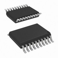
IC, DIGITAL ISOLATOR, 60NS, SSOP-20
Manufacturer
Analog Devices Inc
Series
iCoupler®r
Datasheet
1.EVAL-ADUM3471EBZ.pdf
(32 pages)
Specifications of ADUM3470CRSZ
No. Of Channels
4
Propagation Delay
60ns
Supply Current
33mA
Supply Voltage Range
3V To 3.6V, 4.5V To 5.5V
Digital Ic Case Style
SSOP
No. Of Pins
20
Operating Temperature
-40°C ~ 105°C
Inputs - Side 1/side 2
4/0
Number Of Channels
4
Isolation Rating
2500Vrms
Voltage - Supply
3.3V, 5V
Data Rate
25Mbps
Output Type
Logic
Package / Case
20-SSOP (0.200", 5.30mm Width)
Rohs Compliant
Yes
Lead Free Status / RoHS Status
Lead free / RoHS Compliant
Lead Free Status / RoHS Status
Lead free / RoHS Compliant


ADuM3470/ADuM3471/ADuM3472/ADuM3473/ADuM3474
POWER CONSUMPTION
The V
channels, as well as to the power converter. For this reason, the
quiescent currents drawn by the data converter and the primary
and secondary I/O channels cannot be determined separately. All
of these quiescent power demands have been combined into the
I
equal to the sum of the quiescent operating current; the dynamic
current, I
I
Dynamic I/O current is consumed only when operating a channel
at speeds higher than the refresh rate of f
each channel is determined by its data rate. Figure 18 and Figure 22
show the current for a channel in the forward direction, meaning
that the input is on the V
show the current for a channel in the reverse direction, meaning
that the input is on the V
Figure 22, and Figure 23 assume a typical 15 pF output load.
The following relationship allows the total I
where:
I
I
E is the power supply efficiency at the given output load from
Figure 13 or Figure 17 at the V
I
Figure 18, Figure 19, Figure 22, or Figure 23, depending on
channel direction.
The maximum external load can be calculated by subtracting
the dynamic output load from the maximum allowable load.
where:
I
side load.
I
available at V
I
output or input channel, as shown for a single supply in Figure 20
or Figure 21 or for a double supply in Figure 24 or Figure 25.
CC (Q)
ISO
CC
ISO
CHn
ISO (LOAD)
ISO (MAX)
ISO (D)n
is the total supply input current.
is the current drawn by the secondary side external load.
load.
is the current drawn by a single channel determined from
I
I
I
I
CC (Q)
CC (D)
current, as shown in Figure 45. The total I
CC
ISO (LOAD)
CC
is the dynamic load current drawn from V
= (I
is the maximum external secondary side load current
power supply input provides power to the i Coupler data
is the current available to supply an external secondary
CC (D)
Figure 45. Power Consumption Within the ADuM347x
ISO
= I
ISO
, demanded by the I/O channels; and any external
CONVERTER
× V
PRIMARY
PRIMARY
.
I
ISO (MAX)
DATA
DDP(D)
4CH
I/O
ISO
)/(E × V
CC
− Σ I
ISO
side of the part. Figure 19 and Figure 23
side of the part. Figure 18, Figure 19,
CC
ISO (D)n
FB
) + Σ I
ISO
and V
; n = 1 to 4
CONVERTER
SECONDARY
SECONDARY
CHn
DATA
r
4CH
. The dynamic current of
I/O
; n = 1 to 4
CC
I
ISO(D)
condition of interest.
DD1
CC
current to be
supply current is
ISO
I
ISO
by an
Rev. 0 | Page 30 of 32
(2)
(1)
The preceding analysis assumes a 15 pF capacitive load on each
data output. If the capacitive load is larger than 15 pF, the additional
current must be included in the analysis of I
POWER CONSIDERATIONS
Soft Start Mode and Current-Limit Protection
When the ADuM347x first receives power from V
start mode, and the output voltage V
while it is below the startup threshold. In soft start mode, the
width of the PWM signal is increased gradually by the primary
converter to limit the peak current during V
the output voltage is larger than the startup threshold, the PWM
signal can be transferred from the secondary controller to the
primary converter, and the dc-to-dc converter switches from
soft start mode to the normal PWM control mode. If a short
circuit occurs, the push-pull converter shuts down for about 2
ms and then enters soft start mode. If, at the end of soft start, a
short circuit still exists, the process is repeated, which is called
hiccup mode. If the short circuit is cleared, the ADuM347x
enters normal operation.
The ADuM347x also has a pulse-by-pulse current limit, which
is active in startup and normal operation, and protects the primary
switches, X1 and X2, from exceeding approximately 1.2 A peak
and also protects the transformer windings.
Data Channel Power Cycle
The ADuM347x data input channels on the primary side and the
data input channels on the secondary side are protected from
premature operation by UVLO circuitry. Below the minimum
operating voltage, the power converter holds its oscillator inactive,
and all input channel drivers and refresh circuits are idle. Outputs
are held in a low state. This is to prevent transmission of undefined
states during power-up and power-down operations.
During application of power to V
is held idle until the UVLO preset voltage is reached. At that time,
the data channels are initialized to their default low output state
until they receive data pulses from the secondary side.
The primary side input channels sample the input and send a pulse
to the inactive secondary output. The secondary side converter
begins to accept power from the primary, and the V
starts to rise. When the secondary side UVLO is reached, the
secondary side outputs are initialized to their default low state
until data, either a transition or a dc refresh pulse, is received
from the corresponding primary side input. It can take up to
1 μs after the secondary side is initialized for the state of the
output to correlate with the primary side input.
Secondary side inputs sample their state and transmit it to the
primary side. Outputs are valid one propagation delay after the
secondary side becomes active.
Because the rate of charge of the secondary side is dependent on
the soft start cycle, loading conditions, input voltage, and output
voltage level selected, care should be taken in the design to allow
the converter to stabilize before valid data is required.
CC
, the primary side circuitry
ISO
is increased gradually
DD1
ISO
power-up. When
and I
CC
ISO
, it is in soft
ISO (LOAD)
voltage
.
Related parts for ADUM3470CRSZ
Image
Part Number
Description
Manufacturer
Datasheet
Request
R

Part Number:
Description:
±1.7g Dual-Axis IMEMS Accelerometer Evaluation Board
Manufacturer:
Analog Devices Inc
Datasheet:

Part Number:
Description:
Inertial Sensor Evaluation System
Manufacturer:
Analog Devices Inc
Datasheet:
Part Number:
Description:
Manufacturer:
Analog Devices Inc
Datasheet:
Part Number:
Description:
Manufacturer:
Analog Devices Inc
Datasheet:
Part Number:
Description:
Manufacturer:
Analog Devices Inc
Datasheet:
Part Number:
Description:
Manufacturer:
Analog Devices Inc
Datasheet:
Part Number:
Description:
Manufacturer:
Analog Devices Inc
Datasheet:
Part Number:
Description:
Manufacturer:
Analog Devices Inc
Datasheet:
Part Number:
Description:
Manufacturer:
Analog Devices Inc
Datasheet:
Part Number:
Description:
Manufacturer:
Analog Devices Inc
Datasheet:
Part Number:
Description:
Manufacturer:
Analog Devices Inc
Datasheet:
Part Number:
Description:
Manufacturer:
Analog Devices Inc
Datasheet:
Part Number:
Description:
Manufacturer:
Analog Devices Inc
Datasheet: