ACS758ECB-200B-PFF-T Allegro Microsystems Inc, ACS758ECB-200B-PFF-T Datasheet - Page 3
ACS758ECB-200B-PFF-T
Manufacturer Part Number
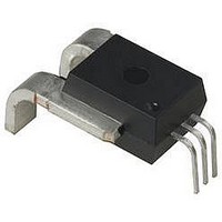
ACS758ECB-200B-PFF-T
Description
IC, HALL EFFECT SENSOR, Linear, PFF
Manufacturer
Allegro Microsystems Inc
Series
ACS758r
Datasheet
1.ACS758ECB-200B-PFF-T.pdf
(20 pages)
Specifications of ACS758ECB-200B-PFF-T
Output Current
3mA
Bandwidth
120kHz
Supply Voltage Max
5.5V
Hall Effect Type
Linear
Operating Temperature Range
-40°C To +85°C
Supply Voltage Min
3V
Package / Case
5-PFF
Current - Sensing
±200A
Accuracy
±1%
Sensitivity
10mV/A
Current - Supply
10mA
Sensor Type
Hall Effect
Voltage - Supply
3 V ~ 5.5 V
Output
2.5V
Frequency
120kHz
Response Time
4µs
Polarization
Bidirectional
Operating Temperature
-40°C ~ 85°C
Lead Free Status / RoHS Status
Lead free / RoHS Compliant


ACS758xCB
Absolute Maximum Ratings
Typical Overcurrent Capabilities
1
2
Thermal Characteristics
Package Thermal Resistance
*Additional thermal information available on the Allegro website
Forward Supply Voltage
Reverse Supply Voltage
Working Voltage for Reinforced Isolation
Working Voltage for Basic Isolation
Forward Output Voltage
Reverse Output Voltage
Output Source Current
Output Sink Current
Nominal Operating Ambient Temperature
Maximum Junction
Storage Temperature
Test was done with Allegro evaluation board. The maximum allowed current is limited by T
For more overcurrent profiles, please see FAQ on the Allegro website, www.allegromicro.com.
Overcurrent
Characteristic
Characteristic
Characteristic
may require derating at maximum conditions
1,2
V
V
I
OUT(Source)
Symbol
I
WORKING-R
WORKING-B
Symbol
T
Thermally Enhanced, Fully Integrated, Hall Effect-Based
Linear Current Sensor IC with
Symbol
OUT(Sink)
V
V
J
V
V
I
RIOUT
T
(max)
T
IOUT
R
POC
RCC
stg
CC
OP
θJA
Mounted on the Allegro evaluation board with
2800 mm
1400 mm
nected to the primary leadframe and with thermal
vias connecting the copper layers. Performance
is based on current flowing through the primary
leadframe and includes the power consumed by
the PCB.
Voltage applied between pins 1-3 and 4-5;
tested at 3000 VAC for 1 minute according to
UL standard 60950-1
Voltage applied between pins 1-3 and 4-5;
tested at 3000 VAC for 1 minute according to
UL standard 60950-1
VIOUT to GND
VCC to VIOUT
Range E
Range K
Range L
T
T
T
A
A
A
= 25°C, 1s duration, 1% duty cycle
= 85°C, 1s duration, 1% duty cycle
= 150°C, 1s duration, 1% duty cycle
2
2
(1400 mm
on opposite side) of 4 oz. copper con-
Test Conditions*
2
Notes
Notes
on component side and
J
(max) only.
100 μΩ
115 Northeast Cutoff
1.508.853.5000; www.allegromicro.com
Allegro MicroSystems, Inc.
Worcester, Massachusetts 01615-0036 U.S.A.
–40 to 125
–40 to 150
–65 to 165
–40 to 85
Rating
Value
Rating
Current Conductor
1200
–0.5
–0.5
353
500
165
900
600
28
8
3
1
7
VDC / V
VDC / V
Units
Units
Unit
ºC/W
mA
mA
ºC
ºC
ºC
ºC
ºC
V
V
V
V
A
A
A
pk
pk
3
Related parts for ACS758ECB-200B-PFF-T
Image
Part Number
Description
Manufacturer
Datasheet
Request
R

Part Number:
Description:
Hall Effect IC
Manufacturer:
Allegro Microsystems Inc
Datasheet:

Part Number:
Description:
200 Amp Uni-Directional Current Sensor
Manufacturer:
Allegro Microsystems Inc
Datasheet:

Part Number:
Description:
IC, HALL EFFECT SENSOR, Linear, SOIC-8
Manufacturer:
Allegro Microsystems Inc
Datasheet:
Part Number:
Description:
IC, HALL EFFECT SENSOR, Linear, SOIC-8
Manufacturer:
Allegro Microsystems Inc
Datasheet:
Part Number:
Description:
IC, HALL EFFECT SENSOR, Linear, SOIC-8
Manufacturer:
Allegro Microsystems Inc
Datasheet:

Part Number:
Description:
IC SWITCH INTERFACE 2CHAN 8-SOIC
Manufacturer:
Allegro Microsystems Inc
Datasheet:
Part Number:
Description:
IC SMOKE DETECTOR ION 16-DIP
Manufacturer:
Allegro Microsystems Inc
Datasheet:
Part Number:
Description:
IC SMOKE DETECTOR ION 16-DIP
Manufacturer:
Allegro Microsystems Inc
Datasheet:
Part Number:
Description:
IC SMOKE DETECTOR ION 16-DIP
Manufacturer:
Allegro Microsystems Inc
Datasheet:
Part Number:
Description:
IC SMOKE DETECTOR PHOTO 16-DIP
Manufacturer:
Allegro Microsystems Inc
Datasheet:
Part Number:
Description:
IC SMOKE DETECTOR ION 16-DIP
Manufacturer:
Allegro Microsystems Inc
Datasheet:
Part Number:
Description:
IC SMOKE DETECTOR PHOTO 16-DIP
Manufacturer:
Allegro Microsystems Inc
Datasheet:
Part Number:
Description:
IC SMOKE DETECTOR PHOTO 16-DIP
Manufacturer:
Allegro Microsystems Inc
Datasheet:
Part Number:
Description:
IC SMOKE DETECTOR ION 16-DIP
Manufacturer:
Allegro Microsystems Inc
Datasheet:
Part Number:
Description:
IC SMOKE DETECTOR PHOTO 16-SOIC
Manufacturer:
Allegro Microsystems Inc
Datasheet: