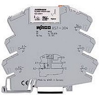
857-354 WAGO, 857-354 Datasheet - Page 6

857-354
Manufacturer Part Number
857-354
Description
POWER RELAY, 1CO, 24VDC, 5A, DIN RAIL
Manufacturer
WAGO
Datasheet
1.857-303.pdf
(12 pages)
Specifications of 857-354
Relay Type
Miniature
Coil Voltage Vac Nom
24V
Coil Voltage Vdc Nom
24V
Contact Current Max
6A
Contact Voltage Ac Nom
250V
Contact Configuration
SPCO
Coil Type
AC / DC
Coil Current
8.5mA
Lead Free Status / RoHS Status
Lead free / RoHS Compliant
Signal Conditioners
Item no.
Configuration
Input signal
Sensor connection
Measuring range
Cold junction compensation
Output signal
Output signal (can be inverted)
Load impedance
Step response
Supply voltage U
Additional configuration options for 857-801/857-811 Series via configuration software
• Selection of additional sensor types
• Inversion of output signal
• Adjustable step response
Module width:
Test voltage:
Transmission error:
Supply Voltage:
Temperature range:
Approvals:
*pending
Jumpers for 857 Series Signal Conditioning and Relay Module
Jumper Comb, Insulated White, 18A
2 Pole
3 Pole
4 Pole
5 Pole
6 Pole
7 Pole
8 Pole
9 Pole
10 Pole
Red insulated part number adder
Blue insulated part number adder
Example, Blue insulated 2 pole
Technical Data for Signal Conditioners
<______________ 94 mm/3.68 in ______________>
N
6.0 mm/0.236 in
2.5 kV AC / 50 Hz / 1 min
< 0.1 % of full scale value
16.8 V ... 31.2 V
-25 °C ... +70 °C
1, r , g*
Class 1 Div. 2
Groups A, B, C, D
______________
2- and 4-wire: 180ms
LISTED
Signal Conditioner
3-wire: 360ms
DIP switch
857-800
for RTDs
1
2
3
4
IN
–
Pt 100, Pt 200, Pt 500, Pt 1000
0 (2) … 10mA; 0 (4) … 20mA
OUT
POWER
0 (1) … 5V, 0 (2) … 10V,
0 …1 kΩ, 0 … 4.5 kΩ
2-wire, 3-wire, 4-wire
-200°C … +850°C
5
6
7
8
≤ 600 Ω (I-output)
≥ 2 kΩ (U-output)
OUT+
GND 1
Us+
GND 2
24VDC
Part Number
859-402
859-403
859-404
859-405
859-406
859-407
859-408
859-409
859-410
.../000-005
.../000-006
859-402/000-006
–
via configuration software
2- and 4-wire: 60ms ... 3s
configuration software
3-wire: 120ms ... 6s
Signal Conditioner
DIP switch or
857-801
for RTDs
1
2
3
4
IN
OUT
POWER
5
6
7
8
Item no.
Configuration
Input signal
(switchable in a calibrated way)
Output signal
(switchable in a calibrated way)
Load impedance
Max. operating frequency
Supply voltage U
OUT+
GND 1
Us+
GND 2
Cold junction on: 120ms
Cold junction off: 60ms
TC+
TC–
Signal Conditioner
for Thermocouples
N
1
2
3
4
DIP switch
857-810
IN
–
Configuration software
- FDT frame application
- DTM (Device Tool Manager)
WAGO USB service cable
OUT
POWER
Type K: -150°C … +1350°C
0 (2) … 10mA; 0 (4) … 20mA
Type J: -150°C … +1200°C
Isolation Amplifier, Configurable
GND 1
GND 3
Thermocouple of type J, K
0 (1) … 5V, 0 (2) … 10V,
with Zero/Span Adjustment
IN+
Us+
(switchable via DIP switch)
5
6
7
8
on/off (default: on)
0 (1) … 5V, 0 (2) … 10V,
0 (1) … 5V, 0 (2) … 10V,
≤ 600 Ω (I-output)
≥ 2 kΩ (U-output)
OUT+
GND 1
Us+
GND 2
≤ 600 Ω (I-output)
≥ 2 kΩ (U-output)
100Hz / > 5kHz
1
2
3
4
0 (4) … 20mA,
0 (4) … 20mA,
24VDC
DIP switch
IN
857-400
24VDC
POWER
Cold junction on: 120ms ... 6s
Cold junction off: 60ms ... 3s
OUT
via configuration software
configuration software
TC+
TC–
Signal Conditioner
for Thermocouples
5
6
7
8
DIP switch or
1
2
3
4
OUT+
GND 2
Us+
GND 3
857-811
IN
759-370
759-380
750-923
OUT
POWER
0 … +30 V (31.2V U
Isolation Amplifier, Confi
GND 1
GND 3
0 (2) … 10mA, 0 (4) …
-10 … +10V, -20 … +
IN+
5
6
7
8
DO
0 (1) … 5V, 0 (2) …
configuration softw
OUT+
GND 1
Us+
GND 2
with Digital Outp
≤ 600 Ω (I-outpu
≥ 2 kΩ (U-output
1
2
3
4
DIP switch or
IN
U,I
DO
857-401
24VDC
–
POWER
OUT
U,I
IN
;1
5
6
7
8


