RH1B-ULDC12V IDEC, RH1B-ULDC12V Datasheet - Page 12
RH1B-ULDC12V
Manufacturer Part Number
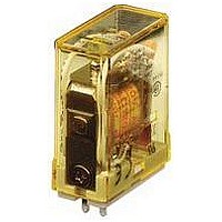
RH1B-ULDC12V
Description
POWER RELAY, SPDT, 12VDC, 10A, PLUG IN
Manufacturer
IDEC
Datasheet
1.RH1B-ULAC24V.pdf
(12 pages)
Specifications of RH1B-ULDC12V
Relay Type
Power
Coil Voltage Vdc Nom
12V
Contact Current Max
10A
Contact Voltage Ac Nom
110V
Contact Voltage Dc Nom
30V
Coil Resistance
188ohm
Contact Configuration
SPDT
Coil Type
DC
Lead Free Status / RoHS Status
Lead free / RoHS Compliant


Relays & Sockets
•
•
•
•
Other Precautions
1. General notice:
Turn off the power to the relay before starting installation, removal, wiring,
maintenance, and inspection of the relays. Failure to turn power off may
cause electrical shock or fi re hazard.
Observe specifi cations and rated values, otherwise electrical shock or fi re
hazard may be caused.
Use wires of the proper size to meet voltage and current requirements. Tight-
en the terminal screws on the relay socket to the proper tightening torque.
Surge absorbing elements on AC relays with RC or DC relays with diode are
provided to absorb the back electromotive force generated by the coil. When
the relay is subject to an excessive external surge voltage, the surge absorb-
ing element may be damaged. Add another surge absorbing provision to the
relay to prevent damage.
To maintain the initial characteristics, do not drop or shock the relay.
The relay cover cannot be removed from the base during normal operation. To
maintain the initial characteristics, do not remove the relay cover.
Use the relay in environments free from condensation, dust, sulfur dioxide
(SO
Make sure that the coil voltage does not exceed applicable coil voltage range.
2
), and hydrogen sulfi de (H
2
S).
USA: 800-262-IDEC
Operating Instructions con’t
Safety Precautions
Canada: 888-317-IDEC
Precautions for the RU Relays
•
•
•
•
2. UL and CSA ratings may differ from product rated values determined by IDEC.
3. Do not use relays in the vicinity of strong magnetic fi eld, as this may affect
Before operating the latching lever of the RU relay, turn off the power to
the RU relay. After checking the circuit, return the latching lever to the
original position.
Do not use the latching lever as a switch. The durability of the latching lever
is a minimum of 100 operations.
When using DC loads on 4PDT relays, apply a positive voltage to terminals of
neighboring poles and a negative voltage to the other terminals of neighbor-
ing poles to prevent the possibility of short circuits.
DC relays with a diode have a polarity in the coil terminals. Apply the DC volt-
age to the correct terminals.
relay operation.
Operating Instructions
775
Related parts for RH1B-ULDC12V
Image
Part Number
Description
Manufacturer
Datasheet
Request
R

Part Number:
Description:
RH Relay SPDT W/ Light & Diode
Manufacturer:
IDEC
Datasheet:
Part Number:
Description:
RELAY MIDGET SPDT 10A 5 BLADE W/LED (NO-UL)
Manufacturer:
IDEC
Part Number:
Description:
Relay; E-Mech; Gen Purp; SPDT; Cur-Rtg 10A; Ctrl-V 24DC; Vol-Rtg 240/30AC/DC; Blade
Manufacturer:
IDEC Corporation
Datasheet:
Part Number:
Description:
Relay; E-Mech; Gen Purp; SPDT; Cur-Rtg 10A; Ctrl-V 110/120AC; Vol-Rtg 240/30AC/DC
Manufacturer:
IDEC Corporation
Datasheet:
Part Number:
Description:
Relay; E-Mech; Gen Purp; SPDT; Cur-Rtg 10A; Ctrl-V 24DC; Vol-Rtg 240/30AC/DC; Blade
Manufacturer:
IDEC Corporation
Datasheet:
Part Number:
Description:
Relay; E-Mech; Gen Purp; SPDT; Cur-Rtg 10A; Ctrl-V 24AC; Vol-Rtg 240/30AC/DC; Blade
Manufacturer:
IDEC Corporation
Datasheet:
Part Number:
Description:
Relay; E-Mech; Gen Purp; SPDT; Cur-Rtg 10A; Ctrl-V 110/120AC; Vol-Rtg 240/30AC/DC
Manufacturer:
IDEC Corporation
Datasheet:
Part Number:
Description:
Relay; E-Mech; Gen Purp; SPDT; Cur-Rtg 10A; Ctrl-V 12DC; Vol-Rtg 240/30AC/DC; Blade
Manufacturer:
IDEC Corporation
Datasheet:
Part Number:
Description:
Relay; E-Mech; Gen Purp; SPDT; Cur-Rtg 10A; Ctrl-V 24AC; Vol-Rtg 240/30AC/DC; Blade
Manufacturer:
IDEC Corporation
Datasheet:
Part Number:
Description:
Relay; E-Mech; Gen Purp; SPDT; Cur-Rtg 10A; Ctrl-V 220/240AC; Vol-Rtg 240/30AC/DC
Manufacturer:
IDEC Corporation
Datasheet:
Part Number:
Description:
INDICATOR INCANDESCENT LAMP, GREEN
Manufacturer:
IDEC
Datasheet:

Part Number:
Description:
LAMP, INDICATOR, INCAND, AMB
Manufacturer:
IDEC
Datasheet:
Part Number:
Description:
LAMP, INDICATOR, INCAND, GRN
Manufacturer:
IDEC
Datasheet:
Part Number:
Description:
LAMP, INDICATOR, INCAND, GRN
Manufacturer:
IDEC
Datasheet:
Part Number:
Description:
LAMP, INDICATOR, INCANDESCENT, RED
Manufacturer:
IDEC
Datasheet: