AGN26012 PANASONIC EW, AGN26012 Datasheet

SIGNAL RELAY, DPDT, 12VDC, 1A, THD

AGN26012

Manufacturer Part Number
AGN26012
Description
SIGNAL RELAY, DPDT, 12VDC, 1A, THD
Manufacturer
PANASONIC EW
Datasheet

Specifications of AGN26012

Contact Configuration
DPDT
Contact Current Max
1A
Contact Voltage Ac Nom
125V
Contact Voltage Dc Nom
30V
Coil Voltage Vdc Nom
12V
Coil Type
DC, Monostable
Coil Current
8.3mA
Lead Free Status / RoHS Status
Lead free / RoHS Compliant
GN (AGN)
ORDERING INFORMATION
Contact arrangement
2: 2 Form C
Operating function
0: Single side stable
1: 1 coil latching
6: High sensitivity single side
Type of operation
0: Standard type (B.B.M.)
Terminal shape
Nil:
A:
S:
Nominal coil voltage (DC)
1H: 1.5V 03: 3V 4H: 4.5V 06: 6V 09: 9V
12: 12V 24: 24V
Packing style
Nil:
X:
Z:
Compliance with RoHS Directive
stable type
Standard PC board terminal
Surface-mount terminal A type
Surface-mount terminal S type
Tube packing
Tape and reel packing (picked from 1/2/3/4 pin side)
Tape and reel packing (picked from 5/6/7/8 pin side)
AGN 2
0
All Rights Reserved © COPYRIGHT Panasonic Electric Works Co., Ltd.
FEATURES
1. Compact slim body saves space
2. High sensitivity single side stable
3. Outstanding surge resistance.
4. The use of twin crossbar contacts
5. Increased packaging density
High Sensitivity of nominal
operating power 100mW is
Thanks to the small surface area of 5.7
mm
and low height of 9.0 mm
the packaging density can be
increased to allow for much smaller
designs.
type (Nominal operating power:
100mW) is available
Surge breakdown voltage between
contacts and coil:
2,500 V 2 10 s (Telcordia)
Surge breakdown voltage between
open contacts:
1,500 V 10 160 s (FCC part 68)
ensures high contact reliability.
AgPd contact is used because of its
good sulfide resistance. Adopting low-
gas molding material. Coil assembly
molding technology which avoids
generating volatile gas from coil.
Due to highly efficient magnetic circuit
design, leakage flux is reduced and
changes in electrical characteristics
from components being mounted
achived. Compact Slim
Body Saves space
10.6 mm
.224 inch
.354
.417 inch
inch,
6. Nominal operating power: 140 mW
7. Outstanding vibration and shock
8. Sealed construction allows
TYPICAL APPLICATIONS
1. Telephone switchboard
2. Telecommunications equipment
3. Security
4. Measurement equipment
5. Consumer electronic and audio
GN RELAYS (AGN)
close-together are minimized. This all
means a packaging density higher
than ever before.
resistance.
Functional shock resistance: 750 m/s
Destructive shock resistance:
1,000 m/s
Functional vibration resistance:
10 to 55 Hz (at double amplitude of
3.3 mm
Destructive vibration resistance:
10 to 55 Hz (at double amplitude of
5 mm
automatic washing.
visual equipment
.197
.130
2
inch)
inch)
TESTING
2

Related parts for AGN26012

AGN26012 Summary of contents

Page 1

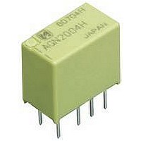
... Due to highly efficient magnetic circuit design, leakage flux is reduced and changes in electrical characteristics from components being mounted All Rights Reserved © COPYRIGHT Panasonic Electric Works Co., Ltd. GN RELAYS (AGN) close-together are minimized. This all means a packaging density higher than ever before. inch, 6 ...

Page 2

... Coil resistance Nominal operating [ 10%] ( power 22.5 90 202.5 100mW 360 810 1,440 4,800 120mW GN (AGN) Part No. AGN2601H AGN26003 AGN2604H AGN26006 AGN26009 AGN26012 AGN26024 Part No. Part No. Max. applied voltage ( 150%V of nominal voltage 120%V of nominal voltage Max. applied voltage ( 150%V of nominal voltage ...

Page 3

GN (AGN) 3) High sensitivity single side stable type Nominal coil Set voltage voltage ( 1. 4.5V DC 80%V or less of 10%V or more nominal voltage* nominal voltage* 9V ...

Page 4

Electrical life (1A 30V DC resistive load) Tested sample: AGN2004H, 6 pcs. Operating speed: 20 cpm Change of pick-up and drop-out voltage 100 90 80 Pick-up voltage Drop-out voltage ...

Page 5

... Please chuck the 80 dia. 3.150 dia. Avoid chucking the center of the relay. In addition, excessive chucking pressure to the pinpoint of the relay should be avoided. For general cautions for use, please refer to the “Cautions for use of Signal Relays” or “General Application Guidelines”. B portion. ...

Related keywords