G5V-2 9DC Omron, G5V-2 9DC Datasheet - Page 2
G5V-2 9DC
Manufacturer Part Number
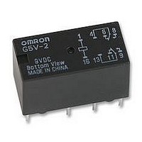
G5V-2 9DC
Description
RELAY, PCB, DPCO, 9VDC
Manufacturer
Omron
Datasheet
1.G5V-2-H1_9DC.pdf
(4 pages)
Specifications of G5V-2 9DC
Contact Current Max
2A
Contact Voltage Ac Nom
125V
Contact Voltage Dc Nom
30V
Coil Voltage Vdc Nom
9V
Coil Resistance
162ohm
Coil Power Cont
500mW
Relay
RoHS Compliant
Coil Type
DC Coil
Coil Current
55.6mA
Contact Configuration
DPCO
Rohs Compliant
Yes


G5V-2
High Sensitivity Models
Note:
■
Note:
■
Note:
Note:
106
Rated voltage
Rated current
Coil resistance
Coil inductance
(H) (ref. value)
Must operate voltage
Must release voltage
Max. voltage
Power consumption
Load
Rated load
Contact material
Rated carry current
Max. switching voltage
Max. switching current
Max. switching power
Failure rate (reference value)
(See note.)
Contact resistance (See note 1.)
Operate time
Release time
Max. operating frequency
Insulation resistance (See note 2.)
Dielectric strength
Impulse withstand voltage
Vibration resistance
Shock resistance
Endurance
Ambient temperature
Ambient humidity
Weight
Contact Ratings
Characteristics
1. The rated current and coil resistance are measured at a coil temperature of 23°C with a tolerance of ±10%.
2. Operating characteristics are measured at a coil temperature of 23°C.
3. The maximum voltage is the highest voltage that can be imposed on the relay coil.
P level:
This value was measured at a switching frequency of 120 operations/min and the criterion of contact resistance is 50 Ω . This value
may vary depending on the switching frequency and operating environment. Always double-check relay suitability under actual op-
erating conditions.
The above values are initial values.
1. The contact resistance was measured with 10 mA at 1 VDC with a voltage drop method.
2. The insulation resistance was measured with a 500-VDC megohmmeter applied to the same parts as those used for checking
the dielectric strength.
λ
60
Item
Item
Armature ON
Armature OFF 0.57
= 0.1 x 10
–6
/operation
3 VDC
50 mA
60 Ω
0.18
75% max. of rated voltage
5% min. of rated voltage
180% of rated voltage at 23°C
Approx. 150 mW
Resistive load (cos φ = 1)
0.5 A at 125 VAC; 2 A at 30 VDC
Ag + Au-clad
2 A
125 VAC, 125 VDC
2 A
62.5 VA, 60 W
0.01 mA at 10 mVDC
50 m Ω max.
7 ms max.
3 ms max.
Mechanical: 36,000 operations/hr
Electrical: 1,800 operations/hr (under rated load)
1,000 M Ω min. (at 500 VDC)
1,000 VAC, 50/60 Hz for 1 min between coil
and contacts
1,000 VAC, 50/60 Hz for 1 min between con-
tacts of different polarity
750 VAC, 50/60 Hz for 1 min between contacts
of same polarity
1,500 V (10 x 160 µs) between coil and contacts (conforms to FCC Part 68)
Destruction: 10 to 55 to 10 Hz, 0.75-mm single amplitude (1.5-mm double amplitude)
Malfunction: 10 to 55 to 10 Hz, 0.75-mm single amplitude (1.5-mm double amplitude)
Destruction: 1,000 m/s
Malfunction: 200 m/s
Mechanical: 15,000,000 operations min. (at 36,000 operations/hr)
Electrical: 100,000 operations min. (at 1,800 operations/hr)
Operating: − 25°C to 65°C (with no icing)
Operating: 5% to 85%
Approx. 5 g
5 VDC
30 mA
166.7 Ω
0.46
0.71
Standard models
Standard models
2
2
(approx. 20G)
6 VDC
25 mA
240 Ω
0.70
0.97
(approx. 100G)
9 VDC
16.7 mA
540 Ω
1.67
2.33
0.5 A at 125 VAC; 1 A at 24 VDC
1 A
62.5 VA, 24 W
100 m Ω max.
1,000 VAC, 50/60 Hz for 1 min between coil
and contacts
1,000 VAC, 50/60 Hz for 1 min between con-
tacts of different polarity
500 VAC, 50/60 Hz for 1 min between contacts
of same polarity
Destruction: 1,000 m/s
Malfunction: 100 m/s
Operating: − 25°C to 70°C (with no icing)
12 VDC
12.5 mA
960 Ω
2.90
3.99
High sensitivity models
High sensitivity models
24 VDC
8.33 mA
2,880 Ω
6.72
9.27
Approx.
200 mW
2
2
(approx. 10G)
(approx. 100G)
48 VDC
6.25 mA
7,680 Ω
20.1
26.7
150% of rated
voltage at
23°C
Approx.
300 mW
G5V-2
Related parts for G5V-2 9DC
Image
Part Number
Description
Manufacturer
Datasheet
Request
R

Part Number:
Description:
RELAY DPDT 2A 48VDC PCB
Manufacturer:
Omron
Datasheet:

Part Number:
Description:
RELAY PCB DPDT 2A 3VDC SEALED
Manufacturer:
Omron
Datasheet:

Part Number:
Description:
RELAY PC MNT DPDT
Manufacturer:
Omron
Datasheet:

Part Number:
Description:
RELAY DPDT 2A 12V 288 OHM COIL
Manufacturer:
Omron
Datasheet:
Part Number:
Description:
RELAY DPDT 2A 24V 1152 OHM COIL
Manufacturer:
Omron
Datasheet:
Part Number:
Description:
RELAY DPDT 2A 5V 50 OHM COIL
Manufacturer:
Omron
Datasheet:

Part Number:
Description:
RELAY PCB DPDT 2A 6VDC
Manufacturer:
Omron
Datasheet:
Part Number:
Description:
LOW SIGNAL RELAY
Manufacturer:
Omron
Datasheet:

Part Number:
Description:
Manufacturer:
Omron Corporation
Datasheet:

Part Number:
Description:
LOW SIGNAL RELAY
Manufacturer:
Omron
Datasheet:
Part Number:
Description:
LOW SIGNAL RELAY
Manufacturer:
Omron
Datasheet:
Part Number:
Description:
LOW SIGNAL RELAY
Manufacturer:
Omron
Datasheet:
Part Number:
Description:
LOW SIGNAL RELAY
Manufacturer:
Omron
Datasheet:
Part Number:
Description:
LOW SIGNAL RELAY
Manufacturer:
Omron
Datasheet: