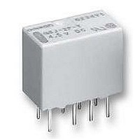
G6J-2PY 3DC Omron, G6J-2PY 3DC Datasheet
G6J-2PY 3DC
Specifications of G6J-2PY 3DC


Related parts for G6J-2PY 3DC


G6J-2PY 3DC Summary of contents
Page 1
... Refer to pages for details. Ordering Information Classification DPDT Plastic sealed PCB terminal Surface mount terminal Short G6J-2FS-Y Note: 1. When ordering, add the rated coil voltage to the model number. Example: G6J-2P-Y 12 VDC Rated coil voltage 2. When ordering tape packing, add “-TR” to the model number. ...
Page 2
... The rated current and coil resistance are measured at a coil temperature of 23°C with a tolerance of ±10%. 2. The operating characteristics are measured at a coil temperature of 23°C. 3. The maximum voltage is the highest voltage that can be imposed on the Relay coil instantaneously. Single-winding Latching Relays (G6JU-2P-Y, G6JU-2FS-Y, G6JU-2FL-Y) Rated voltage 3 VDC Rated current 33 ...
Page 3
... Always double-check relay suitability under actual load conditions. Single-side Stable Relays G6J-2P-Y, G6J-2FS-Y, G6J-2FL-Y 2 (approx. 100G) 2 (approx. 75G) 100,000 operations min. (with a rated load at 1,800 operations/hour) G6J-Y Single-winding Latching Relays G6JU-2P-Y, G6JU-2FS-Y, G6JU-2FL max. (approx. 0.9 ms ...
Page 4
... Conditions: Shock is applied in ±X, ±Y, and ±Z directions three times each with and without energizing the Relays to check the number of contact malfunctions. Contact Reliability Test (See notes 1 and 2.) 1,000 Sample: G6J-2P-Y NO contact Number of Relays: 10 Test conditions: 10 µA resistive load NC contact 500 ...
Page 5
... Average value Average value Operate voltage Release voltage Average value + +20 +10 0 −10 −20 Sample: G6J-2P-Y Operate voltage Number of Relays: 5 Release voltage −30 −1,200 −800 −400 0 400 800 1,200 External magnetic field (A/m) High-frequency Characteristics (Return Loss, V.SWR) (See notes 1 and 2.) ...
Page 6
... Time (ms) Note: The tests were conducted at an ambient temperature of 23°C. 86 Operate and Release Bounce Time Distribution (See note.) 40 Operate bounce time 35 Release bounce time Sample: G6J-2P-Y Number of Relays 0.5 1 1.5 2 2.5 Time (ms) G6J-Y Vibration Resistance 5.0 4.0 3.0 2.0 1 ...
Page 7
... Note: Each value has a tolerance of ±0.3 mm. G6J-Y Terminal Arrangement/ Internal Connections (Bottom View) G6J-2P-Y 7.6 Eight, 0.85-dia. Orientation mark 5.4 holes 3 3.2 − (1.25) G6JU-2P-Y Orientation mark − − Terminal Arrangement/ Internal Connections (Top View) G6J-2FS-Y 7.6 5.4 Orientation mark 2. − ...
Page 8
... A 330 80 Enlarged View of Section A 88 Carrier Tape Dimensions G6J-2FS-Y, G6JU-2FS-Y 16± 2± 0.1 Stopper (green) A 6.2± 0.1 5° max. G6J-2FL-Y, G6JU-2FL-Y 16± 2± 0.1 A 7.9± 0.1 Orientation mark 5° max. Pulling direction 0.5 1 dia. 13± 0.2 ± ...
Page 9
... Contact form Coil rating DPDT G6J-2P-Y, 2FS-Y, 2FL- VDC G6JU-2P-Y, 2FS-Y, 2FL- VDC • The thickness of cream solder to be applied should be between 150 and 200 µ OMRON's recommended PCB pattern. • In order to perform correct soldering recommended that the correct soldering conditions be maintained as shown below on the left-hand side ...
Page 10
... Relays mounted on PCBs may be coated or washed. Do not apply silicone coating or detergent containing silicone, otherwise the silicone coating or detergent may remain on the surface of the Relays. Other Handling Please don’t use the relay if it suffered the dropping shock. Because there is a possibility of something damage for initial performance. G6J-Y ...