61-3440.4/2 EAO, 61-3440.4/2 Datasheet
61-3440.4/2
Specifications of 61-3440.4/2


Related parts for 61-3440.4/2


61-3440.4/2 Summary of contents
Page 1
... Switches and Indicators 61 61 ...
Page 2
... Switches and Indicators Index Series 61 Description Product Assembly Product Range Technical Data Technical Drawing / Dimension / Layouts Circuit Drawing Typical Applications Marking 108 01.2000 - pushbuttons for standard mounting - pushbuttons for flush mounting - asseccories / spare parts Page 109 Page 110 Page 111 Page 117 ...
Page 3
... Spare keys for KABA locks may be ordered under no. 14-987 (please state the lock number). Specimen order Indicator complete - indicator complete, soldering terminal Recommended accessories: - lens plastic mm, clear - LED, 6 chips, 6 VDC, yellow 10-5306.3254 61 61 61-0030.02 61-9331.7 109 01.2000 ...
Page 4
... Product Assembly illuminated-/pushbutton illuminated-/pushbutton for flush mounting 110 01.2000 1 lens 2 actuator case 3 fixing nut 4 switching element 1 lens 2 acutator housing 3 front bezel 4 sealing 5 front panel 6 fixing bow 7 fixing nut 8 switching element 61 ...
Page 5
... technical drawing as of page 140, mounting dimensions as of page 145, circuit drawing as of page 150 dia part no. part no. part no. part no. 61-0030.02 61-0050.02 61-0010.02 61-0020.02 131 dia part no. part no. part no. part no. 61-0039.0 61-0059.0 61-0019.0 61-0029 dia. e part no. 61-0040. 0,005 24 mm dia. e part no. 61-0049 0,005 111 01.2000 ...
Page 6
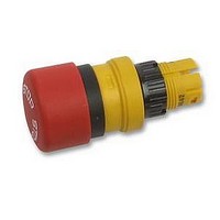
... 61-1130.0 61-1150.0 61-1110.0 61-1330.0 61-1350.0 61-1310.0 130 134 unlocking marking of mushroom-head cap main twist to release arrows stop main key to release stop dia. part no. part no. 61-1220.0 61-1240 0,005 61-1120.0 61-1140 0,005 61-1320 0,005 27 mm dia. part no. 61-3440.4 0,003 61-3440.4 0,003 61-5441.4 0,038 e e ...
Page 7
... ...
Page 8
... A A C+A+B C+B main-0-mom mom-0-main A A+B B mom-0-mom part no. 61-2601.0 0,003 61-2604.0 0,003 61-2602.0 0,003 61-2603.0 0,003 61-2605.0 0,003 61-2607.0 0,003 61-2606.0 0,003 61-2701.0 0,003 61-2703.0 0,003 61-2705.0 0,003 61-2801.0 0,003 61-2804.0 0,003 61-2802.0 0,003 61-2501.0 0,003 ...
Page 9
... C: momentary action pos. A: basic position switching action: main = maintained action, mom = momentary action technical drawing as of page 140, mounting dimensions as of page 145, circuit drawing as of page 150 129 18 mm dia. part no. main 61-4210 mom 61-4110 115 01.2000 0,006 0,006 ...
Page 10
... B: momentary action switching action: mom = momentary, main = maintaining basic position technical drawing as of page 140, mounting dimensions as of page 145, circuit drawing as of page 150 116 01.2000 130 main-0-main main-0-mom mom-0-main mom-0-mom dia. e part no. 61-4610 0,006 61-4710 0,006 61-4810 0,006 61-4510 0,006 ...
Page 11
... ST/PT 61-0000.02 131 part no. 61-0009 0,006 0,005 117 01.2000 ...
Page 12
... technical drawing as of page 140, mounting dimensions as of page 145, circuit drawing as of page 150 118 01.2000 124; lens metal 124 129 , 126 129 61 e part no. mom/main 61-1300 0,005 mom 61-1100 0,005 main 61-1200 0,005 e part no. mom/main 61-1300 0,006 mom 61-1100 0,006 main 61-1200 0,006 ...
Page 13
... A 61-2201.0/D C 61-2203.0 61-2205.0/D mom A 61-2101.0 0,003 0,003 0,003 5 12 ...
Page 14
... A 61-2701.0 61-2703.0 61-2705.0 main-0-main A 61-2601.0 A+B 61-2604.0 61-2602 ...
Page 15
... A: basic position pos. C: momentary action pos. A: basic position switching action: main = maintained action, mom = momentary action technical drawing as of page 140, mounting dimensions as of page 145, circuit drawing as of page 150 129 part no. main 61-4210 mom 61-4110 121 01.2000 0,006 0,006 ...
Page 16
... B: momentary action switching action: mom = momentary, main = maintaining basic position technical drawing as of page 140, mounting dimensions as of page 145, circuit drawing as of page 150 122 01.2000 130 main-0-main main-0-mom mom-0-main mom-0-mom 61 e part no. 61-4610 0,006 61-4710 0,006 61-4810 0,006 61-4510 0,006 ...
Page 17
... 61-9321.3 61-9331.3 61-9351.3 61-9311.3 61-9321.2 61-9331.2 61-9351.2 61-9311.2 61-9331.1 61-9311.1 61-9351.1 61-9321.1 61-9331.4 61-9351.4 61-9311.4 61-9321.4 61-9236.9 61-9226.9 61-9231.9 61-9251.9 61-9211.9 61-9221.9 61-9236.0 61-9226.0 61-9236.8 61-9226.8 61-9231.0 61-9251.0 61-9211.0 61-9221.0 61-9231.8 61-9251.8 61-9211.8 61-9221 dia. e part no. 0,001 0,001 0,001 0,001 0,001 ...
Page 18
... matt lens metal shape lens metal flat matt mushroom-head cap mushroom mushroom-head cap opaque plastic keylock front bezel for keylock switch actuator keylock front bezel 61-9250.0 not for flush mounting 124 01.2000 colour part no. part no. blue 61-9681.6 61-9671.6 colourless, clear 61-9681.7 61-9671 ...
Page 19
... with marking dot and transparent bar lever for flush mounting lever for flush mounting with marking dot and transparent bar marking plate for lens round, 61-9642... marking plate clear, of plastic, can be hot pressed front bezel for selector switch square front material ...
Page 20
... aluminium 61-9931.4 61-9930.4 plated black 61-9931.0 61-9930.0 61-9933.10 natural 61-9932.0 black 61-9932.1 aluminium 61-9931.4 61-9930.4 plated black 61-9931.0 61-9930.0 61-9932.10 natural 61-9932.0 black 61-9932.1 61-9936.0 61-9932.10 colour black natural colour transparent colour transparent part no. part no. part no. 51-925 61-9920.0 51-920 61 e 0,006 ...
Page 21
... for mounting hole 22.5 mm dia. mounting dimensions as of page 145 part no. 61-9922 dia. part no. part no. part no. 51-947.0 61-9450.0 51-949 colour part no. part no. black 61-9451.0 black 61-9452.0 black part no. 61-9921.0 0,006 part no. 51-948.0 1 0,003 28 mm dia. e part no. 3 0,006 3 0,006 704.960.7 3 0,006 127 01.2000 61 ...
Page 22
... circuit drawing as of page 150 diode element diode element with soldering-/plug-in terminal components layouts as of page 146, circuit drawing as of page 150 128 01.2000 e part no. 31-985.0 e part no. 14-987.1001 0,006 31-989.311 0,006 e part no. 31-989.300 0,006 e part no. 61-8006.01 1 0,005 e part no. 1 61-8101. 0,007 2 61-8102. 0,008 61 ...
Page 23
... 26 5 0,007 61-8430. 0,007 61-8430. 0,007 61-8640. 0,008 61-8610. 0,008 61-8212. 0,007 61-8212. 0,007 61-8640. 0,008 61-8670. 0,008 61-8610. 0,008 61-8650. 0,008 61-8620. 0,008 61-8640. 0,008 61-8670. 0,008 61-8610. 0,008 61-8650. 0,008 61-8620. 0,008 61-8645. 0,008 61-8675. 0,008 61-8615. 0,008 61-8655.11 24 ...
Page 24
... 61-8775. 0,008 61-8755. 0,008 61-8745. 0,008 61-8775. 0,008 61-8755. 0,008 e part no. 61-8574. 0,008 61-8574. 0,008 61-8550. 0,008 61-8550. 0,008 61-8520. 0,008 61-8520. 0,008 61-8770. 0,008 61-8750. 0,008 61-8720. 0,008 61-8770. 0,008 61-8750. 0,008 61-8720. 0,008 61-8775. 0,008 61-8755. 0,008 61-8725. 0,008 61 ...
Page 25
... VAC/ VAC/DC pin orientation axial axial axial connection method plug in terminal 2,8 x 0,5 mm plug-in terminal 2,8 x 0,5 mm for multi-plug housing 61 e part no. ST 61-8000.05 e part no. 61-9820.1 27 0,002 61-9823 29 0,002 61-9821.1 28 0,003 e part no. 61-9830 0,002 e part no. 31-946 0,001 51-943.1 0,001 131 01.2000 61 ...
Page 26
... 0,002 e part no. 10-1306.1349 (41-963.0) 0,001 10-1307.1369 (31-963.0) 0,001 10-1309.1309 (41-963.1) 0,001 10-1310.1319 (31-963.1) 0,001 10-1311.1249 (41-963.2) 0,001 10-1312.1229 (41-963.3) 0,001 10-1313.1209 (41-963.4) 0,001 10-1313.1249 (31-963.2) 0,001 10-1316.1179 (41-963.36) 0,001 10-1316.1209 (31-963.5) 0,001 10-1319.1179 (41-963.5) 0,001 10-1319.1199 (31-963.3) 0,001 10-1320.1179 (31-963.4) 0,001 61 ...
Page 27
... VDC/24 mA green 10-6309.3185 (61-995.5) red 10-6309.3182 (61-995.2) yellow 10-6309.3184 (61-995.4) 24 VDC/12 mA green 10-6312.3105 (61-996.5) red 10-6312.3102 (61-996.2) yellow 10-6312.3104 (61-996.4) 28 VDC/12 mA green 10-6313.3105 (96-997.5) red 10-6313.3102 (61-997.2) yellow 10-6313.3104 (61-997.4) 24 VDC/14 mA white 10-2312.3139 28 VDC/14 mA white 10-2313 ...
Page 28
... 0,135 02-914.40 0,180 e part no. 02-913.10 0,040 02-913.20 0,075 02-913.30 0,115 02-913.40 0,155 02-913.11 0,040 02-913.21 0,075 02-913.31 0,115 02-913.41 0,155 02-913.17 0,040 02-913.27 0,075 02-913.37 0,115 02-913.47 0,155 43 mm dia. e part no. 61-9970.3 0,002 61-9970.2 0,002 61-9970.1 0,002 61-9970.0 0,002 e part no. 61-9965 ...
Page 29
... K61-999.100 e part no. 61-9730.0 0,011 02-905 0,011 135 01.2000 61 ...
Page 30
... mounting tool for tightening (or loosening) fixing nuts cable shoe remover cable shoe remover for removing the connector from the multi-plug housing 136 01.2000 61 e part no. 61-9740.0 0,003 e part no. 51-938 0,027 61-9832 0,024 e part no. 61-9711.0 0,004 e part no. 01-907 0,020 e part no. 51-943.9 0,001 ...
Page 31
... DC, L:R=30 ms: rated service voltage: rated service current resistive: rated service current L:R=30ms: 2 solder- volume resistance starting value (initial) for: gold-/silver contact < silver contact <= 100 250 VAC 125 VAC 110 VAC 220 110 60 24 VDC 0.5 0.7 2 ...
Page 32
... Technical Data rules IEC 1058 EN 61 058 approvals - SEV 250 VAC CSA 300 VAC - UR 250 VAC VDE 250 VAC German Lloyd actuator with slow-make switching element switching system Self-cleaning, double-break, snap-action switching elements (con- tact gap 2 x 1.5 mm). The elements can be supplied with the following choice of switching ...
Page 33
... DIN IEC 68-) connection method soldering terminal 2.8 x 0.8 mm electrical characteristics flashing frequency 1 Hz ± 0.25 Hz illumination incandescent lamp Multi-LED 12.5 mA making cycle 1:1 operating voltage 10 10 VAC VDC 2,0 6,0 A 1.0 2 139 01.2000 ...
Page 34
... Technical Drawing, Dimension, Layout technical drawing 1 indicator complete page 111 2 indicator-/flasher-actuator page 111 3 illuminated-/pushbutton actuator page 112 140 01.2000 61 ...
Page 35
... Technical Drawing, Dimension, Layout 4 emergency stop switch actuator foolproof page 112 5 pushbutton actuator with mushroom-head cap page 113 61 61 141 01.2000 ...
Page 36
... Technical Drawing, Dimension, Layout 6 keylock switch actuator 2 positions, keylock switch actuator 3 positions page 113, 114 7 selector switch actuator 2 positions, selector switch actuator 3 positions page 115, 116 8 indicator complete for flush mounting page 117 142 01.2000 61 ...
Page 37
... Technical Drawing, Dimension, Layout 9 indicator-/flasher-actuator for flush mounting page 117 10 illuminated-/pushbutton actuator for flush mounting page 118 11 mushroom pushbutton actuator for flush mounting page 118 61 61 143 01.2000 ...
Page 38
... 12 keylock switch actuator with 2 positions for flush mounting, keylock switch actuator 3 positions for flush mounting page 119, 120 13 selector switch actuator 2 positions for flush mounting, selector switch actuator 3 positions for flush mounting page 121, 122 14 protective cover page 126 15 protective cover page 126 144 01.2000 61 ...
Page 39
... mounting, keylock switch actuator with 2 positions for flush mounting, keylock switch actuator 3 positions for flush mounting, selector switch actuator 2 positions for flush mounting, selector switch actuator 3 positions for flush mounting, blind plug flat page 117,118,119,120, 121, 122, 127 61 61 145 01.2000 ...
Page 40
... 6 switching element for illuminated-/pushbutton, keylock-/selector switch 2 positions page 129 7 switching element for illuminated-/pushbutton, keylock-/selector switch 2 positions page 129 8 switching element for illuminated-/pushbutton, keylock-/selector switch 2 positions page 129 9 switching element for illuminated-/pushbutton, keylock-/selector switch 2 positions page 129 146 01.2000 61 ...
Page 41
... 15 switching element for illuminated-/pushbutton, keylock-/selector switch 2 positions page 129 16 switching element for illuminated-/pushbutton, keylock-/selector switch 2 positions page 129 17 switching element for illuminated-/pushbutton, keylock-/selector switch 2 positions page 129 18 switching element for emergency stop switch page 130 61 61 147 01.2000 ...
Page 42
... PCB plug-in base page 131 148 01.2000 61 ...
Page 43
... Technical Drawing, Dimension, Layout 28 PCB plug-in base page 131 29 PCB plug-in base page 131 61 61 149 01.2000 ...
Page 44
... Circuit Drawing circuit drawing 150 01.2000 circuit drawing ...
Page 45
... Typical Applications With indicators and illuminated pushbuttons equipped with diodes, the user is able to perform a lamp check or wire an alarm circuit simply with a considerable saving of space 151 01.2000 ...
Page 46
... Typical Applications Flasher element 152 01.2000 61 ...
Page 47
... A list of the symbols available can be sup- plied on request. Important! Before engraving, check the position of the illuminated pushbutton or indicator (Ø 18) Ø 15,8 mm Vertical mounting (caps) (small) (caps 2-3 2 Ø 12 (18 x 18) 15,3 x 15,3 mm (small) (caps) (small 2-3 2-3 b 12,7 x 12,7 mm 153 01.2000 ...
Page 48
... Film b dimen- sion 154 01.2000 . ( mm Horizontal mounting (caps) (small) (caps) (small 7 10-11 11-12 4 4 3-4 3-4 a 16,9 x 16 ( Vertical mounting (caps) (small) (caps) (small 8 7 2-3 2-3 1 2-3 b 15 4-5 4 2-3 ...