3007W2SCM99A30X Conec, 3007W2SCM99A30X Datasheet - Page 4
3007W2SCM99A30X
Manufacturer Part Number
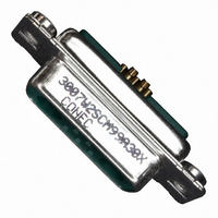
3007W2SCM99A30X
Description
CONN DSUB COMBO 7POS 7W2 SOCKET
Manufacturer
Conec
Specifications of 3007W2SCM99A30X
Connector Style
D-Sub, Combo
Number Of Positions
7
Number Of Rows
2
Shell Size, Connector Layout
2 (DA, A) - 7W2
Contact Type
Signal
Connector Type
Receptacle, Female Sockets
Mounting Type
Free Hanging (In-Line)
Flange Feature
Housing/Shell (4-40)
Termination
Solder Cup
Features
Coax/Power Contacts not Included
Shell Material, Finish
Steel, Tin Plated
Contact Finish
Gold
Contact Finish Thickness
30µin (0.76µm)
Operating Temperature
-55°C ~ 125°C
Voltage Rating
250V
Current Rating
5A
Housing Material
Polybutylene Terephthalate, Glass Filled (PBT)
Color
Green
Product
Mixed Contact Hoods & Connectors
Shell Plating
Tin
Shell Size
2
Gender
Female
Mounting Style
Panel
Mounting Angle
Straight
Termination Style
Solder Cup
Contact Arrangement
7W2S
Contact Material
Copper Alloy
Lead Free Status / RoHS Status
Lead free / RoHS Compliant
Other names
626-1115
Available stocks
Company
Part Number
Manufacturer
Quantity
Price
Company:

Part Number:
3007W2SCM99A30X
Manufacturer:
Conec
Quantity:
173


Part Number Creator
Product Line
3
1
A
Shell size and design
1
2
3
4
5
Contact type
P
S
Oberfläche Quality class for signal contacts
A
B
C
J
X
Termination only for signal contacts
K
M
N
P
R
T
Mounting style
A1
A2
A3
A4
A5
A6
A7
A8
C1
C2
C3
C4
C5
C6
D1
D2
D3
D4
D5
D6
E1
E2
E3
E4
E5
Termination for high power or coaxial contacts
C1
C2
C3
C4
61 41 = Solder cup 10 A
62 42 = Solder cup 20 A
63 43 = Solder cup 30 A
64 44 = Solder cup 40 A
68 48 = Solder pin, straight 20 A, D= .077“ 1.95 mm
69 49 = Solder pin, straight 20 A, D= .102“ 2.60 mm
70 50 = Solder pin, straight 20 A, D= .110“ 2.85 mm
71 51 = Solder pin, straight 30 A, D= .130“ 3.18 mm
72 52 = Solder pin, straight 40 A, D= .150“ 3.75 mm
59 55 = Solder pin, angled 15 A
73 56 = Solder pin, angled 20 A
74 57 = Solder pin, angled 30 A
OX = Standard
= Shell steel tin plated
= Brass tin plated*
= Stainless steel*
= 5W1, 2W2C
= 3W3, 7W2, 11W1, 3W3C
= 5W5, 9W4, 13W3, 17W2, 21W1
= 8W8, 13W6, 17W5, 21WA4, 25W3, 27W2
= 24W7, 36W4, 43W2, 47W1
= Plug connector
= Socket connector
= Quality class 3 = 50 mating cycles
= Quality class 2 = 200 mating cycles
= Quality class 1 = 500 mating cycles
= Special application = > 500 mating cycles (on request)
= Crimp and 3W3, 5W5, 8W8, 2W2C, 3W3C (no contacts are supplied with the connector)
= Crimp without contacts
= Solder cup
= Wire wrap, .500“ 12.7 mm
= Press fit
= Solder pin, straight, .220" 5.6 mm
= Solder pin, angled, .280“ 7.19 mm
= Solder Crimp angled 10 A
= Riveted
= M3 threaded insert
= 4-40 UNC threaded insert
= M3 threaded rear spacer
= 4-40 UNC threaded rear spacer
= Float fastening
= Threaded rear spacer for M3 press fit
= Threaded rear spacer for 4-40 UNC press fit
= M3 threaded rear spacer with PCB clip, PCB .063“ 1.60 mm
= 4-40 UNC threaded rear spacer with PCB clip, PCB .063“ 1.60 mm
= M3 threaded rear spacer with PCB clip, PCB .091“ 2.30 mm
= 4-40 UNC threaded rear spacer with PCB clip, PCB .091“ 2.30 mm
= M3 threaded rear spacer with PCB clip, PCB .126“ 3.20 mm
= 4-40 UNC Threaded rear spacer with PCB clip, PCB .126“ 3.20 mm
= M3 clip and threaded rear spacer with PCB clip, PCB .063“ 1.60 mm
= 4-40 UNC clip and threaded rear spacer with PCB clip, PCB .063“ 1.60 mm
= M3 clip and threaded rear spacer with PCB clip, PCB .091“ 2.30 mm
= 4-40 UNC clip and threaded rear spacer clip, PCB .091“ 2.30 mm
= M3 clip and threaded rear spacer with PCB clip, PCB .126“ 3.20 mm
= 4-40 UNC clip and threaded rear spacer with PCB clip, PCB .126“ 3.20 mm
= M3 threaded rear spacer with PCB clip, PCB .063“ 1.60 mm
= 4-40 UNC threaded rear spacer with PCB clip, PCB .063“ 1.60 mm
= M3 threaded rear spacer with PCB clip, PCB .091“ 2.30 mm
= 4-40 UNC threaded rear spacer with PCB clip, PCB .091“ 2.30 mm
= M3 threaded rear spacer with PCB clip, PCB .126“ 3.20 mm
= Solder Crimp angled 20 A
= Solder Crimp angled 30 A
= Solder Crimp angled 40 A
*on request
Empty positions ADD „0“ = 003W3
U
W*
X
Z*
*
75 58 = Solder pin, angled 40 A
77 60 = Solder pin, angled 40 A
85 65 = Solder pin, angled 30 A
81 66 = Solder pin, angled 20 A
82 67 = Solder pin, angled 30 A
G7 76 = 3 Solder pins Straight 50 Ω
G9 78 = 3 Solder pins angled 50 Ω
H1 79 = 3 Solder pins angled 50 Ω
H4 80 = 5 Solder pins angled 50 Ω
G8 86 = 3 Solder pins Straight 75 Ω
H2 88 = 3 Solder pins angled 75 Ω
H3 89 = 3 Solder pins angled 75 Ω
H5 90 = 5 Solder pins angled 75 Ω
91
99
Coaxial contacts with cable termination must be ordered separately.
E6
F1
F2
F3
F4
F5
F6
G1
G2
G3
G4
H1
H2
H3
H4
N1
N2
N3
N4
P1
P2
P3
P4
W1
W2
= Solder pin, angled, .370“ 9.40 mm
= Solder pin, angled, .450“ 11.43 mm
= 3W3, 5W5, 8W8, 2W2C, 3W3C
= Solder pin, angled, .540“ 13.84 mm
= please contact us
= Screw termination 20 A
= no high power, coax or crimp contacts loaded
= 4-40 UNC threaded rear spacer with PCB clip, PCB .126“ 3.20 mm
= M3 clip and threaded rear spacer with PCB clip, PCB .063“ 1.60 mm
= 4-40 UNC clip and threaded rear spacer with PCB clip, PCB .063“ 1.60 mm
= M3 clip and threaded rear spacer with PCB clip, PCB .091“ 2.30 mm
= 4-40 UNC clip and threaded rear spacer with PCB clip, PCB .091“ 2.30 mm
= M3 clip and threaded rear spacer with PCB clip, PCB .126“ 3.20 mm
= 4-40 UNC clip and threaded rear spacer with PCB clip, PCB .126“ 3.20 mm
= Metal bracket, M3 threaded insert for .370“ 9.40 mm
= Metal bracket, 4-40 UNC threaded insert for .370“ 9.40 mm
= Metal bracket, M3 threaded insert and clip for .370“ 9.40 mm
= Metal bracket, 4-40 UNC threaded insert and clip for .370“ 9.40 mm
= Metal bracket, M3 threaded lock for .370“ 9.40 mm
= Metal bracket, 4-40 UNC threaded lock for .370“ 9.40 mm
= Metal bracket, M3 threaded lock and clip for .370“ 9.40 mm
= Metal bracket, 4-40 UNC threaded lock and clip for .370“ 9.40 mm
= Metal bracket, M3 threaded insert for .280“ 7.19 mm
= Metal bracket, 4-40 UNC threaded insert for .280“ 7.19 mm
= Metal bracket, M3 threaded insert and clip for .280“ 7.19 mm
= Metal bracket, 4-40 UNC threaded insert and clip for .280“ 7.19 mm
= Metal bracket, M3 threaded lock for .280“ 7.19 mm
= Metal bracket, 4-40 UNC threaded lock for .280“ 7.19 mm
= Metal bracket, M3 threaded lock and clip for .280“ 7.19 mm
= Metal bracket, 4-40 UNC threaded lock and clip for .280“ 7.19 mm
= Threaded rear spacer with M3 press in pin
= Threaded rear spacer with 4-40 UNC press in pin
3
003W3 S
C om bin ati on D-S UB C o n n e ct o rs
X
X
6
1 A
1
O
X
6 | 3
Related parts for 3007W2SCM99A30X
Image
Part Number
Description
Manufacturer
Datasheet
Request
R

Part Number:
Description:
Combination D-SUB without contacts, For straight high power, coaxial or high voltage contacts
Manufacturer:
CONEC [CONEC Elektronische Bauelemente GmbH]
Datasheet:
Part Number:
Description:
CompactPCI
Manufacturer:
CONEC [CONEC Elektronische Bauelemente GmbH]
Datasheet:
Part Number:
Description:
D-SUB FEMALE 90� 15pos. SOLDER PIN ANGLED with metal bracket, hexlocking screw and snap
Manufacturer:
CONEC [CONEC Elektronische Bauelemente GmbH]
Datasheet:
Part Number:
Description:
D-SUB MALE 90� 15pos. SOLDER PIN ANGLED with metal bracket, hexlocking screw and snap
Manufacturer:
CONEC [CONEC Elektronische Bauelemente GmbH]
Datasheet:
Part Number:
Description:
D-SUB MALE 15pos. SOLDER CUP with hexlocking screw
Manufacturer:
CONEC [CONEC Elektronische Bauelemente GmbH]
Datasheet: