SCR1100-D04 VTI Technologies, SCR1100-D04 Datasheet - Page 10
SCR1100-D04
Manufacturer Part Number
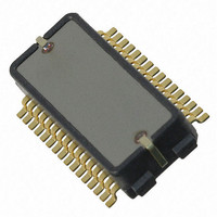
SCR1100-D04
Description
SENSOR GYRO 300DEG SNGL AXIS SPI
Manufacturer
VTI Technologies
Datasheet
1.SCR1100-D04.pdf
(21 pages)
Specifications of SCR1100-D04
New! Us2012 Catalog Page
Single Axis Gyroscopes
Range °/s
±300°/s
Sensitivity
18LSB/°/s
Typical Bandwidth
50Hz
Voltage - Supply
3 V ~ 3.6 V, 4.75 V ~ 5.25 V
Current - Supply
20mA, 26mA
Output Type
Analog, Digital
Operating Temperature
-40°C ~ 125°C
Package / Case
32-SOP
Lead Free Status / RoHS Status
Lead free / RoHS Compliant
Other names
551-1077-2


Register Result:
4.1.2
VTI Technologies Oy
www.vti.fi
D15
reg 14
SPI Transfer Parity Mode
D14
reg 13
reg[14:0] :
par odd :
Figure 6 shows an example of communication sequence:
Figure 5. Communication example.
Each communication frame in the figure 6 contain 16 SCK cycles. After communication start
(CSN_G falling edge) the master sends ADR1 and performs a read access. In parallel the slave
sends Status Flags. During the transmission of the next data word (ADR2) the slave sends the
register value of ADR1 (Result_1). On ADR2 the master performs a write access (RW='1'). The
slave stores Data_2 in the register of ADR2 and sends the current register value of ADR2 to
MISO_G. After the transmission of data value during a write access the slave always sends Status
Flags. To receive Result_5 of the last read access the Master has to send an additional word ('Zero
Vector').
SCR1100 gyro ASIC is able to support parity check during SPI Transfer. This functionality is
controlled by the IC Identification Register. The internal parity status is reported in Status/Config
Register.
With parity enable bit set the SCR1100 gyro ASIC is expecting an additional parity bit after the
transmission of each 16 bit data word. This additional parity bit requires an additional SCK cycle,
i.e. the SPI frame consists of 17 SCK cycles instead of the normal 16 SCK cycles. Detecting a
wrong parity bit has the following consequences:
During read access:
The Parity Error Flag in the Status/Config Register is set. The SCR1100 reports the contents of the
received register address.
During write access:
The Parity Error Flag in the Status/Config Register is set. The SPI Write Access is cancelled.
These actions are performed either if the parity failure is detected in the address word or the data
word.
Due to the additional parity bit a single SPI Transfer is using now 17 Bit as shown in the Figure 7.
Figure 6. Communication in parity mode.
D13
reg 12
D12
reg11
value of the internal register. All bits, which are not used, are set to zero.
see Address Transfer
D11
reg 10
Doc.Nr. 82 1226 00 A
Subject to changes
D10
reg9
D9
reg8
D8
reg7
D7
reg6
D6
reg5
D5
reg4
D4
reg3
D3
reg2
D2
reg1
D1
reg0
SCR1100-D04
D0
par
odd
Rev. 0.3
10/21
Related parts for SCR1100-D04
Image
Part Number
Description
Manufacturer
Datasheet
Request
R

Part Number:
Description:
Manufacturer:
Samtec Inc
Datasheet:
Part Number:
Description:
Manufacturer:
Samtec Inc
Datasheet:
Part Number:
Description:
SEALED CIRCULAR POWER RECEPTACLE
Manufacturer:
Samtec Inc

Part Number:
Description:
ACCELEROMETER SGL 1.7G DIL8 SMD
Manufacturer:
VTI Technologies
Datasheet:

Part Number:
Description:
VTI Automotive Digital Accelerometer Platform
Manufacturer:
VTI [VTI technologies]
Datasheet:

Part Number:
Description:
BOARD PWB ACCEL 3-AXIS SPI/I2C
Manufacturer:
VTI Technologies
Datasheet:

Part Number:
Description:
EVAL BOARD ACCELEROMETER Y-AXIS
Manufacturer:
VTI Technologies
Datasheet:

Part Number:
Description:
EVAL BOARD INCLINOMETER Y-AXIS
Manufacturer:
VTI Technologies
Datasheet:
Part Number:
Description:
ACCELEROMETER SGL 1.7G DIL8 SMD
Manufacturer:
VTI Technologies
Datasheet:
Part Number:
Description:
VTI Automotive Digital Accelerometer Platform
Manufacturer:
VTI [VTI technologies]
Datasheet:
Part Number:
Description:
Accelerometer
Manufacturer:
VTI [VTI technologies]
Datasheet:
Part Number:
Description:
Stand Alone Inclinometer
Manufacturer:
VTI [VTI technologies]
Datasheet:
Part Number:
Description:
3-axis accelerometer
Manufacturer:
VTI [VTI technologies]
Datasheet: