ATS617LSGTN-T Allegro Microsystems Inc, ATS617LSGTN-T Datasheet - Page 11
ATS617LSGTN-T
Manufacturer Part Number
ATS617LSGTN-T
Description
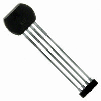
IC HALL EFFECT GEAR SENSOR 4SIP
Manufacturer
Allegro Microsystems Inc
Type
Special Purposer
Datasheet
1.ATS617LSGTN-T.pdf
(16 pages)
Specifications of ATS617LSGTN-T
Package / Case
4-SIP
Sensing Range
60G
Voltage - Supply
4.5 V ~ 24 V
Current - Supply
12mA
Current - Output (max)
55mA
Output Type
Digital, Open Collector
Features
Gear Tooth Type
Operating Temperature
-40°C ~ 150°C
Output Current
45mA
Bandwidth
15kHz
Supply Voltage Max
24V
Hall Effect Type
Gear Tooth
Operating Temperature Range
-40°C To +150°C
Supply Voltage Min
4.5V
Lead Free Status / RoHS Status
Lead free / RoHS Compliant
Other names
620-1326-2
Available stocks
Company
Part Number
Manufacturer
Quantity
Price


ATS617LSG
Assembly Description The ATS617 gear-tooth sensor IC is a
Hall IC/rare-earth pellet configuration that is fully optimized to
provide detection of gear tooth edges. This device is packaged in
a molded miniature plastic body that has been optimized for size,
ease of assembly, and manufacturability. High operating tem-
perature materials are used in all aspects of construction.
After proper power is applied to the component, the chip is
capable of instantly providing digital information that is repre-
sentative of the profile of a rotating gear. No additional optimi-
zation or processing circuitry is required. This ease of use should
reduce design time and incremental assembly costs for most
applications.
Hall Technology The ATS617 contains a single-chip dif-
ferential Hall effect sensor IC, a samarium cobalt pellet, and a
flat ferrous pole piece (figure 2). The Hall IC consists of 2 Hall
elements (spaced 2.2 mm apart) located so as to measure the
magnetic gradient created by the passing of a ferrous object. The
two elements measure the magnetic gradient and convert it to an
analog voltage that is then processed in order to provide a digital
output signal.
The Hall IC is self-calibrating and also possesses a tempera-
ture compensated amplifier and offset cancellation circuitry. Its
voltage regulator provides supply noise rejection throughout the
operating voltage range. Changes in temperature do not greatly
affect this device due to the stable amplifier design and the offset
Figure 2. Relative motion of the target is detected by the dual Hall ele-
ments mounted on the Hall IC.
Hall Effect Device
Target (Gear)
Hall Element 2
Dual-Element
(Pin n >1 Side)
South Pole
North Pole
Dynamic, Self-Calibrating, Peak-Detecting, Differential
(Pin 1 Side)
(Concentrator)
Element Pitch
Hall Element 1
Hall IC
Pole Piece
Back-Biasing
Rare-Earth Pellet
Case
Functional Description
rejection circuitry. The Hall transducers and signal processing
electronics are integrated on the same silicon substrate, using a
proprietary BiCMOS process.
Internal Electronics The processing circuit uses a patented
peak detection scheme to eliminate magnet and system offsets.
This technique allows dynamic coupling and filtering of offsets
without the power-up and settling time disadvantages of classical
high-pass filtering schemes. The peak signal of every tooth and
valley is detected by the filter and is used to provide an instant
reference for the operate and release point comparator. In this
manner, the thresholds are adapted and referenced to individual
signal peaks and valleys, providing immunity to zero line varia-
tion from installation inaccuracies (tilt, rotation, and off-center
placement), as well as for variations caused by target and shaft
eccentricities.
The ATS617 also includes self-calibration circuitry that is
engaged at power on. The signal amplitude is measured, and
then the device gain is normalized. In this manner switchpoint
drift versus air gap is minimized, and excellent timing accuracy
can be achieved.
The AGC (Automatic Gain Control) circuitry, in conjunction
with a unique hysteresis circuit, also eliminates the effect of gear
edge overshoot as well as increases the immunity to false switch-
ing caused by gear tooth anomalies at close air gaps. The AGC
circuit sets the gain of the device after power-on.
Figure 3. The peaks in the resulting differential signal are used to set the
operate, B
Differential
Input Signal
V
Device Output
V
PROC
OUT
Hall Effect Gear Tooth Sensor IC
V
OUT(sat)
OP
V
V+
0
V–
, and release, B
CC
RP
115 Northeast Cutoff
1.508.853.5000; www.allegromicro.com
Allegro MicroSystems, Inc.
Worcester, Massachusetts 01615-0036 U.S.A.
, switchpoints.
B
OP
B
RP
B
OP
B
RP
11
Related parts for ATS617LSGTN-T
Image
Part Number
Description
Manufacturer
Datasheet
Request
R

Part Number:
Description:
IC, HALL EFFECT SENSOR, Linear, SOIC-8
Manufacturer:
Allegro Microsystems Inc
Datasheet:
Part Number:
Description:
IC, HALL EFFECT SENSOR, Linear, SOIC-8
Manufacturer:
Allegro Microsystems Inc
Datasheet:
Part Number:
Description:
IC, HALL EFFECT SENSOR, Linear, SOIC-8
Manufacturer:
Allegro Microsystems Inc
Datasheet:

Part Number:
Description:
IC SWITCH INTERFACE 2CHAN 8-SOIC
Manufacturer:
Allegro Microsystems Inc
Datasheet:

Part Number:
Description:
IC SMOKE DETECTOR ION 16-DIP
Manufacturer:
Allegro Microsystems Inc
Datasheet:
Part Number:
Description:
IC SMOKE DETECTOR ION 16-DIP
Manufacturer:
Allegro Microsystems Inc
Datasheet:
Part Number:
Description:
IC SMOKE DETECTOR ION 16-DIP
Manufacturer:
Allegro Microsystems Inc
Datasheet:
Part Number:
Description:
IC SMOKE DETECTOR PHOTO 16-DIP
Manufacturer:
Allegro Microsystems Inc
Datasheet:
Part Number:
Description:
IC SMOKE DETECTOR ION 16-DIP
Manufacturer:
Allegro Microsystems Inc
Datasheet:
Part Number:
Description:
IC SMOKE DETECTOR PHOTO 16-DIP
Manufacturer:
Allegro Microsystems Inc
Datasheet:
Part Number:
Description:
IC SMOKE DETECTOR PHOTO 16-DIP
Manufacturer:
Allegro Microsystems Inc
Datasheet:
Part Number:
Description:
IC SMOKE DETECTOR ION 16-DIP
Manufacturer:
Allegro Microsystems Inc
Datasheet:
Part Number:
Description:
IC SMOKE DETECTOR PHOTO 16-SOIC
Manufacturer:
Allegro Microsystems Inc
Datasheet:

Part Number:
Description:
IC LED DRIVER HIGH BRIGHT 16-QFN
Manufacturer:
Allegro Microsystems Inc
Datasheet:

Part Number:
Description:
IC LED DRIVER AUTOMOTIVE 8-SOIC
Manufacturer:
Allegro Microsystems Inc
Datasheet: